Basic HTML Version


ATTACH THE BACKBOX
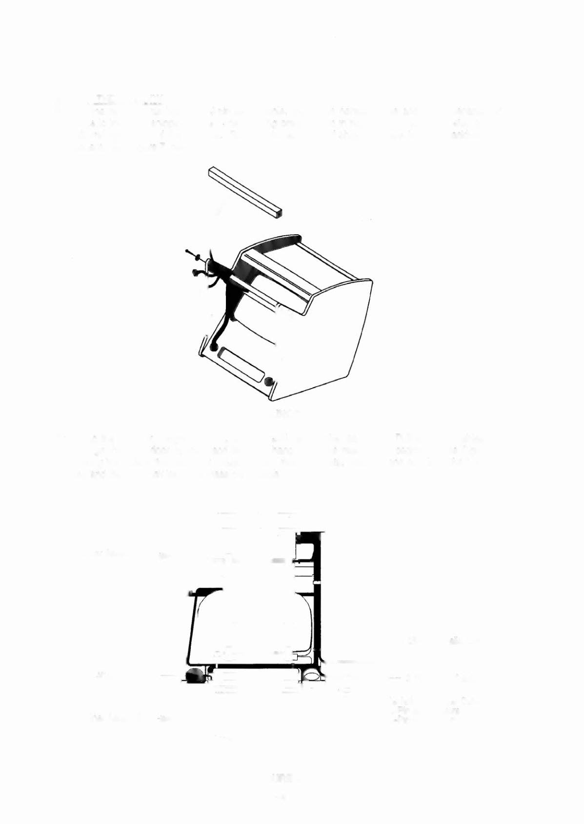
6. Cut the tie-wrap that holds the g-pin serial cable, the 25-pin parallel cable and the power/speaker
cable to the wood shipping brace. The shipping brace is held in place by two screws located on the
left and right sides of the backbox. Remove the screws and shipping brace from the backbox and
discard. See Figure 7, below.
FIGURE 7
7. Stand the backbox upright. Unlock, unscrew and remove the rear door. Pull the three cables out
through the back door opening and let them hang down the rear of the backbox. See Figure 8.
Among the parts in the cash box locate the four mounting bolts, washers and bushings, the 1/4
R
hex
key and the
7132
8
hex key. Set these parts aside.
Cabinet Assembly-..
BackboxAssembly~
FIGURES
1-4