Basic HTML Version


TEST/DIAGNOSTIC PROCEDURES
(Continued)
"On" State Logic· Special Solenoid
"Off" State • Special Solenoid:
The Special Switch Trigger Input goes low. Mean-
while, the PIA line remains high. The remaining sig-
nals reverse their states.
"On" State Logic • Controlled Solenoid
"Off" State • Controlled Solenoid:
The Enable Input (from the PIA) goes low. Mean-
the BLANKING signal remains high. The rest of the
signals reverse their states.
NOTE
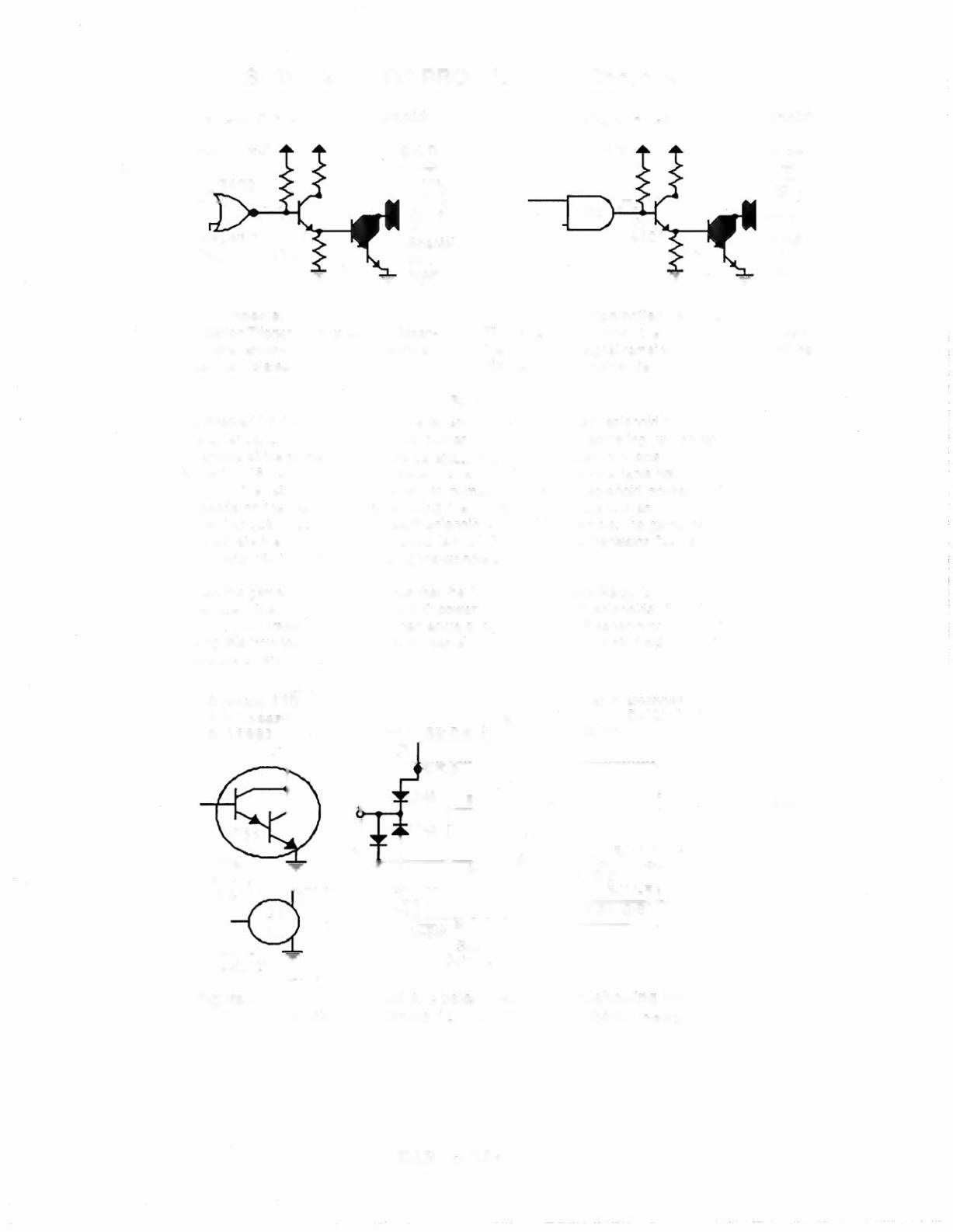
As directed by the game program, the Solenoid AlC Select Relay (solenoid 12) switches
the solenoid B+ power between two power busses to permit actuating two groups of
solenoids at the proper times. In its de-energized state, the Relay connects the 'circuit A
power'to 16 "controlled" and "switched" solenoids (identified in the table with no suffix
letter or the letter A, after the solenoid number). Individual solenoid operation then
depends on the game program enabling the ground path for solenoid actuation via the
driver transistor associated with each solenoid circuit. For example, the game program
can actuate the Outhole Kicker solenoid (sol. 01A), via the driver transistor
033,
when the
ball drains into the outhole, operating the outhole switch.
When the game program determines that the Solenoid AlC Select Relay (sol. 12) must be
energized, the relay connects 'circuit C power' to eight group C solenoids (01C through
08C). Now, driver transistor
033
can actuate the Captive Ball Flasher circuit (sol. 01C).
Using this "multiplexing" technique, the same driver transistor can control actuation of two
separate solenoid circuits.
Orn
Captive BeJl
Flesher
Figure 4. Typical Solenoid AlC Select Relay Circuit, showing the
function of Solenoid 12, the Solenoid AlC Select Relay.
EARTHSHAKER 31