-

-

-
 MY CART
0 item(s)-$00.00
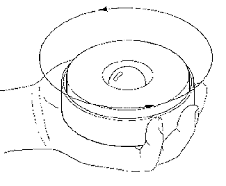
Service Bulletin: SB 85DATE: November 9, 1995 GAME: Johnny Mnemonic SUBJECT: Manual Amendment This amendment updates and/or adds to information in the JOHNNY MNEMONIC Operations Manual. Please keep this amendment with the operations manual. Page 1-43 LED List LED 2 and LED 3 on the Power Driver board are not used. The following troubleshooting information for the Data Glove was not in Section One. Troubleshooting Data Glove Problems. The Data Glove Ball Catcher is an electromagnet. When the ball is shot up to the magnet assembly, the electromagnet is turned on to full power. This enables the magnet assembly to catch the ball even if slight positioning errors or popper inconsistencies occur. Once the ball is in the magnet, the ball closes the "Ball in Hand" switch located inside the magnet. When this switch is closed, the magnet is duty cycled in order to prevent overheating of the coil and to prevent magnetizing the ball. If The Data Glove Does Not Catch The Ball: 1. Verify that the magnet is positioned approximately over the ball popper mechanism, if magnet is not, see the Data Glove Movement troubleshooting section. 2. Check the ball popper assembly located beneath the playfield. Verify that the coil is functional, verify that the opto switch is functional, verify that no wires interfere with the plunger coil movement. This assembly is designed to consistently shoot the ball straight up to the hand. If, from the players vantage point, the popper appears to arc the ball away from the magnet, this implies that the coil is loose, wires are interfering with the plunger, or the entire assembly has been damaged during service. 3. Put the game into the Solenoid test, (be sure the service switch actuator is in place). Hold a ball beneath the magnet assembly. The magnet will grab and release the ball repeatedly. This indicates that the magnet is functional. 4. Check the "Ball in Hand" switch located inside the magnet. Put the game in the Switch test. Hold a ball firmly inside the magnet and roll the ball around inside the magnet cavity. The switch should remain closed as you do this. If the switch opens and closes intermittently, the switch needs to be re-adjusted. To re-adjust the switch, remove the decorative vinyl glove (one Phillips screw). Remove the switch, (remove the 6-32 hex-head screw. Be sure to pull the switch blade down to prevent the switch from getting caught on the core pin), re-adjust the switch blades and re-install the switch. Be careful when re-installing the switch that the fish paper insulator is not damaged or wrinkled. Also verify that the switch does not hang-up on the core pin located in the center of the magnet. The leaf switch should be free throughout the leafs travel. The best way to check adjustment of this switch is to remove the magnet can from the "Y" drive arm, but leave the cable connected. Turn over the assembly in your hand, place a ball inside and roll the ball around checking switch closures while in the switch test. NOTE: Do not press the ball while rolling it around. The switch must actuate due to the weight of the pinball only. Troubleshooting The Data Glove Assembly. The Data Glove consists of three major component assemblies. They are:
The "X" and "Y" drives are similar. The main components of each drive are a DC gear motor, a drive screw with a floating nut, a coupler, a home switch, and a bi-directional optical encoder. The magnet assembly consists of an electromagnet fastened to a sheet metal can. The can has a core pin staked in the center and a leaf switch to detect when a ball is in the magnet. The game diagnostic system is very helpful in determining problems with the system. Each Hand test procedure is described in the Test section of the Operation Manual. To Troubleshoot Data Glove Movement Problems:
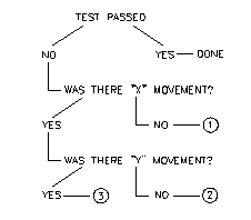
1. Check Fuse 111. 2. Check Fuse 111. 3. Check "X" and/or "Y" home switches. Thank you,
|