Basic HTML Version


SWITCHES
Dedicated
Grounded
Switches
Orange-Brown (1
J205-1
Left Coin Chute 01
Orange-Red
(2
J205-2
Center Coin
Chute
Orange-Black
J205-3
Nhlte
~_Green
t\:
1
2
3
4
5
6
7
8
9
Green-
Green-
Green-
Green-
Green-
Green-
Green-
G•.•• n-
Gray-
Brown
Red
Orange
Yellow Black
Blue
Violet
Gray
White
J2C6-1
J206-2
J206-3 J206-4
J206-5 J206-6
J206-7
J206-9
• J5-1
U20-1B U20-17
U20-16 U20-15
L120-14 U20-13
U20-12
U20-11
w
1 White-
Right
Slam
Left
Dead
Gumball
Lower
Not
Lower
Clock
Brown
Inlane
Ti~
Jet
End
Popper
Skill
Used
Right
15
J208-1
Bumper
Lane
Magnet
Minutes
U1B-ll
11
21
31
41
51
61
71
81
91
2 White-
Right
Coin
Right
The Hrtch-Hiker
Center
Auto-Fire
Not
Clock
Red
Outlane
Door
Jet
Camera
Skill
Kicker
Used
0
J208-2
Closed
Bumper
Minutes
U1B-9
12
22
32
42
S2
62
72
82
82
3 White-
Start
Buy-In
Lower
Player
Left
Upper
Right
Left
Clock
Orange Button
Button
Jel
Piano
Ramp
Skill
Ramp
Magnet
45
J20B-3
Bumper
Enter
Minutes
U1B-S
13
23
33
43
53
63
73
83
93
4 White-
Plumb
Always
Left
Mini
Left
Upper
Gumball
Center
Clock
Yellow Bob
Closed Slingshot
Playfield
Ramp
Right
Popper
Lock
30
J208-4
Tilt
Enter
5 Million
Minutes
U1B-7
14
24
34
44
54
64
74
84
94
5 White-
Right
Far
Right
Mini
Gumball
Power
Mini
Upper
Clock
Green
Trough
Left
Slingshot
Playfield Geneva
Payoff
Playfield
Lock
Hour
J208-S
Trough
Left
(2)
Top
1
U1e-l1
15
25
35
(2) 4S
S5
65
75
85
95
6 White-
Center
Trough
Left
Mini
Gumball
Middle
Mini
Not
Clock
Blue
Trough Proximity Outlane Playfield
Exit
Right
Playfield
Used
Hour
J208-7
Right
5
Million
Exrt
2
U19-9
16
26
36
(2) 46
56
1 66
76
86
96
7 White-
Left
Ball
Left
Clock
Slot
Middle
Middle
Gumball
Clock
Violet
Trough
Shooter
Inlane
Millions Proximity
Right
Left
Enter
Hour
J20B-8
1
SMiliion 5 Million
3
UI9-S
17
27
37
47
S1
2
fiT
n
87
97
8 White-
Outhole
Rocket
Left
Lower
5101
Lower
Upper
Lock
Clock
Gray
Kicker
Inlane
Left
Kickout
Right
Left
Lower
Hour
J208-9
2
5
Million
5
Million 5 Million
4
U19-7
18
28
38
48
58
68
78
88
98
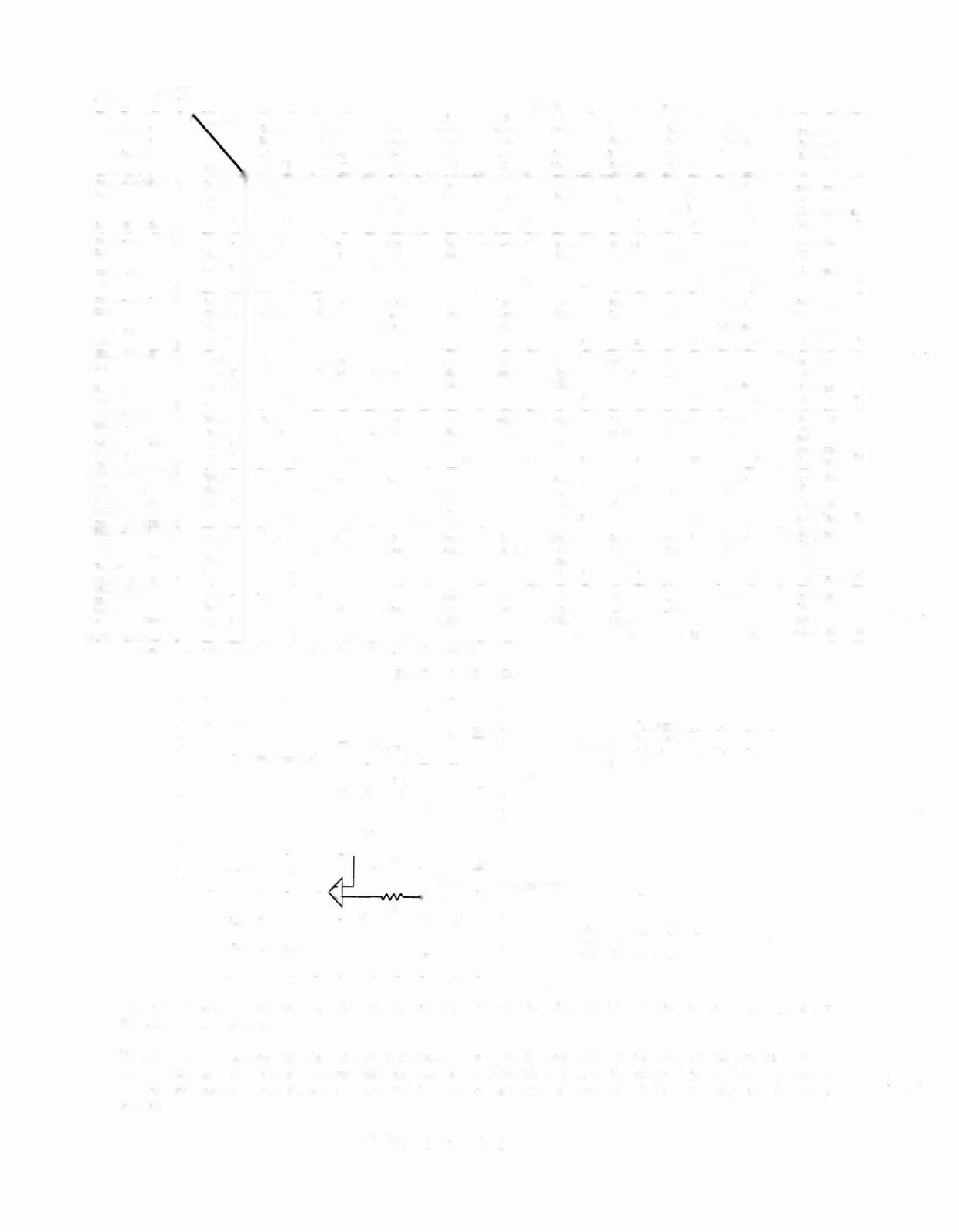
J2XX
=
CPU Board. J9XX
=
Fllptromc II Board
• Located on 8 Dnver P.C.B .• A-I
el
00. In bacl<box_
SWITCH MATRIX CIRCUIT
CPU
Board
RIpper
Grounded
swttchee
Black-Green
J906-1
Right Flipper End
of Stroke
Fl
Blue-Viol.
J905-1
Right Flipper
Opto
F2
Black-Blue
J906-3
Left Flipper
End of Stroke F3
Blue-Gray
J905-2
Left Flipper
Opto
F4
Black-Violet
J906-4
Upper
Right Flipper
End of Stroke F5
Black·Yellow
J90S-3
Upper Right
Flipper Opto F6
Black-Gray
J906-S
Upper
Left Ripper
F7
End of Stroke
Black-Blue
J90S-S
UpperLaft
RipperOpto F8
OIf
On
Inactive
Active
H
L
L
H
Off
On
Playfie/d
Column (example)
C
lK
The microprocessor is constantly strobing the column side of the switch. When point "A' on the column circuit toggles low
the column side is active.
When a switch closes, the row side of the circuit activates. The '+" input to the LM339 drops below +5V causing its output to
go low. Corresponding row and column switches must be low at the same time, for the switch to be considered closed by
the microprocessor. When the switch opens, the "+' input to the LM339 is above +5V, its output is high and the row is
'--,--../
inactive.
Row (example)
1
.6
Twilight Zone 3-2