Basic HTML Version


LAMPS
Yellow (B+)
(j)
Red
~
1
2
3
4
5
6
7
8
Yellow-
Yellow-
Yellow-
Yellow-
Yellow-
Yellow-
Yellow-
Yellow-
Brown
Red
Orange
Black
Green
Blue
Violet
Gray
J137-1
J137-2
J137-3
J137-4
J137-5
J137-6
J138-7
J138-9
w
Q98
Q97
Q96
Q9S
Q94
Q93
Q92
Q91
Red-
Camera
Door
Left
Spiral
Left
Left
Lower
Left
Brown
(Door)
Panel
Extra
'2 MUllon'
RaJ11>
Jet
Right
Spiral
1 J133-1
'Lock
2'
Ball
Bonus X Bu~r
5
MUllon
Q90
11
21
31
41
51
61
71
81
Red-
Hitch
Greed
Door
Spiral Left
Left
Lower
Middle
Clock
Black
Hlcker
(Door)
Panel
Bailie
RaJ11>
Jet
Right
Millions
2 J133·2
(Door)
'Lock
l'
Power
Multball
Bu~r
5
Million
Q89
12
22
32
42
52
62
2
72
82
Red-
Clock
10
Left
Spiral
LefIRaJ11> Right
Middle
Plano
Orange Chaos
Million
Inlane
'4
MIllion'
'Super
Jet
Right
Yellow
3 J133-4
(Door)
(Door)
1
Skill'
Bu~r
5
MUllon
Q88
13
23
33
43
53
63
1 73
83
Red"
Super
Battle The
Door
Spiral
Left
Middle
Power
Plano
Yellow Skill
Power
Handle
Right
PoweroaU Left
Payofl
Red
4 J133-5
(Door)
(Door)
Bailie
5
MUllon
Q87
14
24
34
Power
44
54
64
74
84
Red-
Fast
The
Left
Spiral
The
Upper
Upper
Slot
Green
Lock
Spiral
Inlane
'10
Million'
Cament
Left
Righi
Machine
5 J133-6
(Door)
(Door)
2
5
Million
5
Million
Q86
15
25
3S
45
55
65
75
85
Red-
Lite
Clock
Door
Spiral
Right
Right
Mini
Right
Blue
Gumball
Million
Panel
'Extra
RaJ11> Special
Playfleld
Lane
6 J133-7
(Door)
(Door)
'Gum'
Ball'
The Power
soo.ooo
Gumball
Q85
16
26
36
46
56
66
76
86
Red-
Town
Super
Lower
Shoot
lock
RIght
Mini
Buy-In
Violet
Square
Slot
Left
Again
Extra Powelball
Playfield
Button
7 J133-8
Madness
(Door)
5
Million
BaH
1,000,000
Q84
(Door)
17
27
37
47
57
67
rt
87
Red-
Llle
Door
Dead
Right
Lock
Right
Mini
Start
Gray
Extra Ball
Panal
End
Inlane
Arrow
Lane
Playlleld
Button
8 J133-9
(Door)
'Ball'
Spiral
750,000
Q83
18
28
38
48
58
68
78
88
J1XX
=
Pow.r Drtver Board
LAMP
MATRIX CIRCUIT
r - - - - - - - - - - - - - - - - - - - - - - - - - - - - - -.
I
Power Driver Board
>::eo:=l""umn=_.;.-;A:-tI-!B'I=_
-
H LOff
l
H On
Row (example)
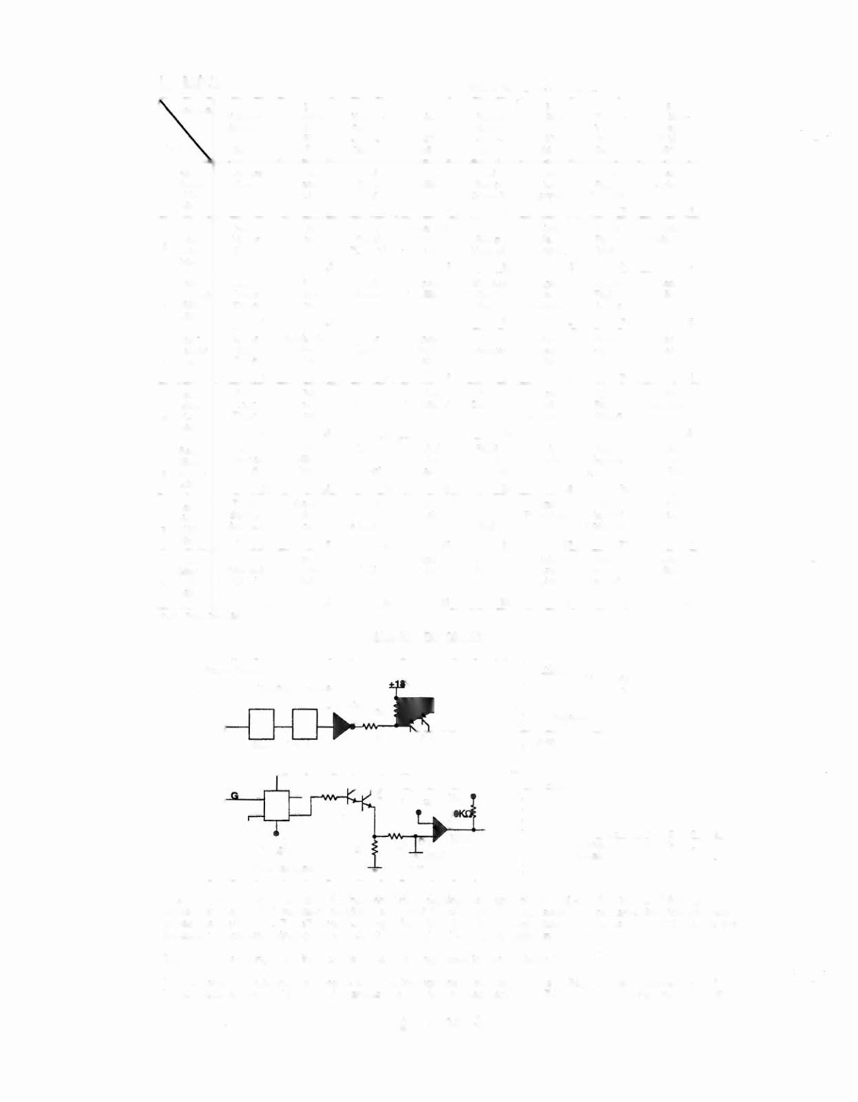
The processor sends a signal to the column circuit, causing the output of the UNL-2S03 to toggle. When point 'A'
drops low, the TIP107 transistor conducts and point 'B' changes to a high state. At the same time the processor
drives the input of the 74LS74 low, causing a high at output 'F'. A high state at the base of TIP102 causes the
transistor to conduct, bringing the row circuit to ground and tuming the lamp On.
The processor changes the input of the 74LS74 to a high state to tum the lamp Off.
In overcurrent conditions the lamp is shut Off through the comparator. If the voltage at the negative input of the
LM339 rises above 1.4V the output changes to a low, which is fed back to the 74LS74 and shuts the row circuit Off.
Twilight Zone 3-4