Basic HTML Version


4. Reach into the cabinet and backbox and ensure that the interconnecting cables are not kinked or
pinched. Be careful to avoid damaging wires at any stage of the assembly process.
5. Raise the hinged backbox upright and latch it into position.
Note:
The insert panel is attached to the speaker panel and is separated from the backbox as a
single unit.
Unlock the backbox and remove the backglass, storing it carefully to avoid damage. Remove the two
foam packing blocks between the backglass and insert panel.
Grasp the upper insert unit and rotate it away from the backbox, toward the playfield glass.
This allows access to the bolt holes used for securing the backbox upright. Install the washer-head
mounting bolts through the bottom holes of the backbox into the threaded fasteners in the cabinet to
secure the backbox.
6. Load the tokens. Lift the insert up at an angle and slowly drop the tokens into the token tube filling
the tube only
%
full. Replace the insert unit, the backglass, and lock the backbox.
IAlcAUTION
FAILURE
TO
INSTALL
the backbox mounting hardware properly can cause personal injury.
NEVER TRANSPORT
a pinball game with the hinged backbox erect. Always lower the backbox
forward onto the playtield cabinet on a layer of protective material to prevent marring or damage and
possible personal injury.
7. Extend each leg leveler slightly below the leg bottom, so that all four foot pads protrude
approximately the same distance. Remove the cabinet from its support and place it on the floor.
8. Unlock and open the coin door. Move the front molding latch lever toward the left side of the game,
to release the front molding. Lift the front molding off the playfield cover glass, return the latch lever
to the right, and close the coin door. Carefully slide the glass downward, until it clears the grooves of
the left and right side moldings. Lift the glass up and away from the game, storing it carefully to avoid
breakage.
9. Place a level or an inclinometer on the playfield surface. Adjust the leg levelers for proper playfield
level (side-to-side). NOTE: These measurements must be made ON the playfield, not the cabinet
nor the playfield cover glass. Tighten the nut on each leg leveler shaft to maintain this setting.
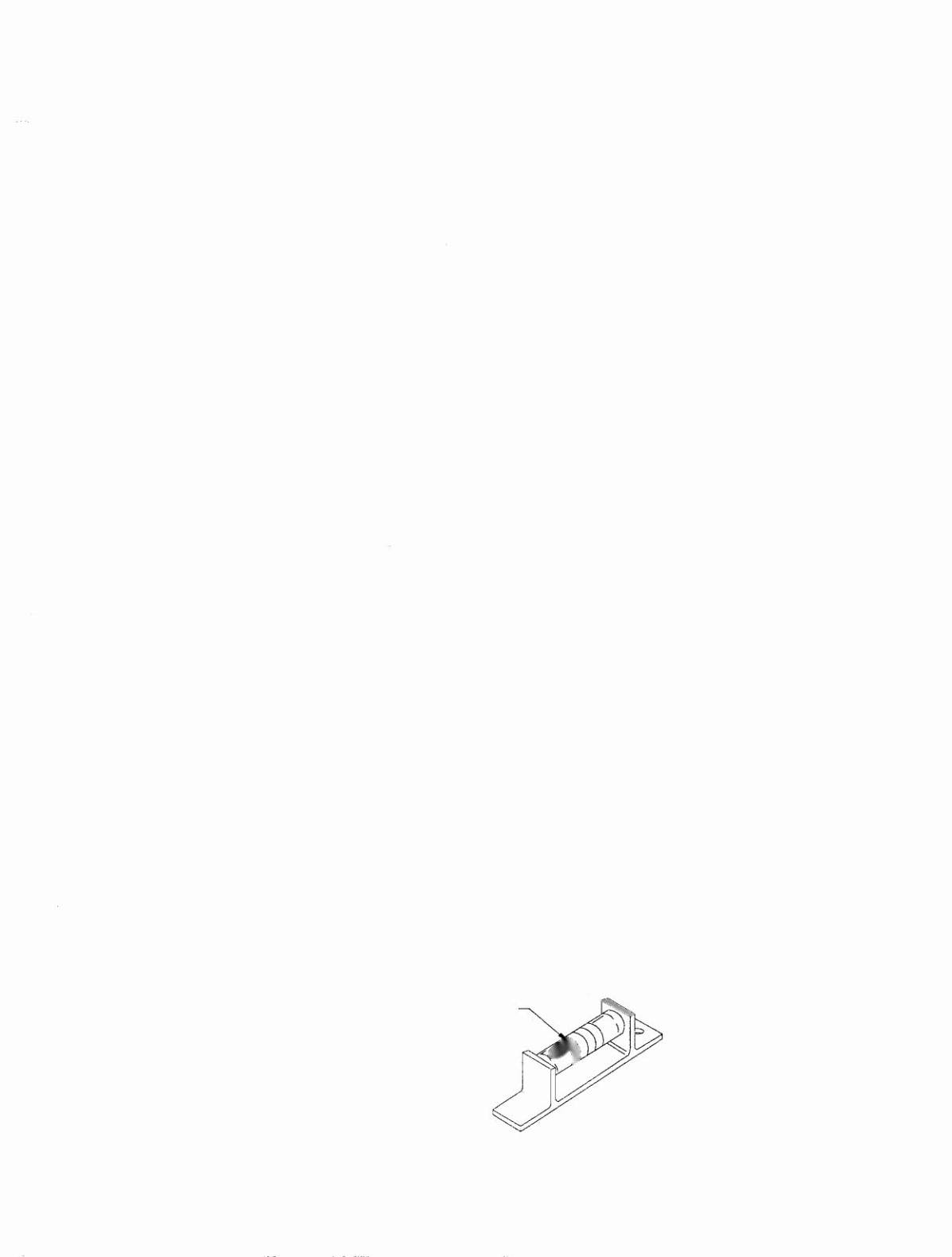
10. The TRU-PITCH™ level is located on the right shooter rail. This allows the playfield pitch angle to be
accurately adjusted WITHOUT REMOVING THE GLASS. The first line (closest to the front of the
game) on the level is approximately 6 degrees. Every line thereafter is approximately another 1/2
degree of pitch. The recommended pitch is 6 1/2 degrees. The nose of the bubble should be
between the first and second line on the level (see diagram below).
TRU-PITCHTU level 6 1/2 degrees.
A-15802-P
1-3