Basic HTML Version


Description
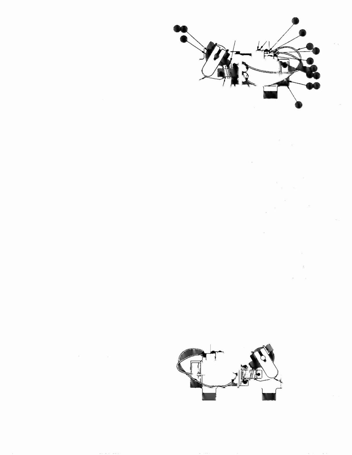
Lower Right Flipper
pIn
C-11626-R-3
Item Part No.
1 HW-30018-6
2 03-7520-2
3 20-6516
4 5045-1 2098-00
5 RM-21 ·06
6 4010-01066-06
7 4701-00004-00
8 A-12111
9 FL-11630
10 4006-01017·04
11 01-7695
12 10-376
13 B-10655-R
a)
02-4179
b)
4010-01086-14
c)
4700-00023-00
d)
4701-00004-00
e)
4410-01132-00
~
A-10656"
1.) 02-4219
2.) 20-9370-1
3.) 03-8050-1
g)
B-10657·R
1.) 01·8073·R
2.) 17-1037
3.) 4010-01066-18
4.) 4410-01127-00
5.) 4700-00107-00
6.) 4701-00004-00
7.) RM-23-06
14 23-6577
15 03-7568
16 4006-01005·06
17 4406-01117-00
18 C-11627-R
19 06-14G
20 4105-01019-10
21 4701-00002-00
22 23-6622
23 03-7811
•• - also see separate diagram
Wire, 18 AWG, Blue
Ty-Wrap, Nylon
Speednut, Tinnerman
Capacitor, 2.2 f.lFd, 250V, 20%
Sleeve, Vinyl (Cap. leads)
Cap Screw, 10-32 x 3/8, SH
Lockwasher, #10 split
Ripper Stop Assembly
Flipper Coil
(. - Refer to Note 3)
Mach. Screw, 6-32
x
1/4, P-RH-S
Solenoid Bracket
Coil Plunger Spring
Crank Link Assembly
Link Spacer Bushing
Cap Screw, 10-32 x 7/8, SH
Washer, 5/8 o.d.
x
13/64 i. d.
x
16 gao
Lockwasher, #10 split
Nut, 10-32 ESNA
Ripper Link Assembly
Coil Plunger
Spring Pin, 5/32 dia. x 7/16
Ripper Link
Flipper Crank Assembly, Right
Flipper Crank, Right
Crank Washer
Cap Screw, 10-32 x 1·1/8, HCS
Nut, 10-32 Hex Hd.
s
Washer, 5/8 o.d. x 13/64 l, d. x 12 gao
Lockwasher, #10 split
6
Tubing, H. S. 1/4 DWP
Bumper Plug
Flipper Bushing
Mach. Screw, 6-32 x 3/8, P-PH
Nut, 6-32 Hex
Ripper Base Assembly, R.
Insulating Blade
She Metal Screw, #5
x
5/8, P-PH-A
Lockwasher, #6 split
Tape, Double-sided
End of Stroke (EOS) Switch
Flipper Assembly Notes:
1 Each Flipper Assembly on the lower PlayliC'ld (and the two
lower Flipper Assemblies on Ihe Upper PI(lyli'!ld) is mounted
beneath the playfiefd. in conjunction with the plactic Flipper
Paddle and Shaft (20·9250-5) and flipper Rubber (23·6519·4)
on the upper side of the playlield. Th" Upp'" Flipper Assembly
on the Upper Playfield uses a plastic Flipper P(lddle and Shaft
(C-11927-5) and flipper Rubber
(23-6553A).
2 The tip of the EOS Switch must travel 0.0150
(+
.010. - 000)
Inch. before the contacts fully open. wilh tb" flipper in the actu-
ated position. The EOS Switch contacts must have a gap
01
0.062 (± .0IS) inch. Adjustment of the EOS Switch must be
made at a minimum distance
01
0.25 inch Irom the swilch body.
3 Flipper Assembly C·11626·R·8 (upper right flipper on Mini·
Playfleld) and C·11626-L-8 (upper
1"lt Ilipp or on Main
Playfield) use a Flipper Coil. FL-11753/50Vc
4 All moving elements of the assembly must oper ate Imely. wi!h
no eVidence of binding.
The large end 01 the Coil Plunger Spring (item 12) must lit within
the four lugs of the Solenoid Bracket
For coil replacement. remove the Solenoid Bracket (item 11) to
prevent screw damage.
7 Use Loct;te'" 242 when reattaching screws to the Flipper Stop
Assembly, the Solenoid Bracket, and the Flipper Bushing
8 When replacing the Bumper Plug (item 14) 10 restore proper
flipper operaflon, readjust the flipper paddle and shaft position
9 Solid color blue wire connects to the banded end of each diode.
mounted on the connector end of lhe Flipper Coil (item 9)c
Trace color wire connects to the unbanded end of th" diode
11
Description
Lower Left Flipper
pin
C-116 26- L-3
(Parts listed replace same Items of C-11626-R-3)
Item Part No.
13
g)
1.)
18
B·10655-L
B-l0657-L
01-8073 L
C-11627-L
Crank Link Assembly
Ripper Crank Assembly, Lett
Flipper Crank, Left
Flipper Base Assy, L.
JOKERZ48