Basic HTML Version


TEST/DIAGNOSTIC PROCEDURES
(Continued)
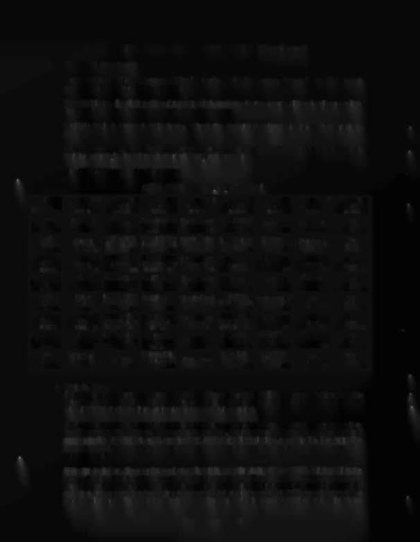
SWITCH TESTS (Continued).
Matrix Table
for switch numbers and wiring information. CPU Board connections at jacks 1J8 (columns)
and 1J10 (rows) are also listed in the table.
Row Problems. If a display of two (or more) switch numbers of a row occurs, although only one switch
is closed, check for a short circuit between the column wires.
Multiple Switch Number Indications.
Check the associated column wire for a short circuit to
ground.
Column Problems.
If display of two (or more) switch numbers in a column occurs (while only one
switch is actuated), check for a short circuit between the row wires.
Use AUTO·UP to proceed to the next test.
HIGH SPEED
Switch-Matrix Table
~
1 045
2 049
3 044
4 048
5 043
6 047
7 042
8 046
GRN·BRN
GRN·RED
GRN·ORN
GRN·VEL
GRN·BLK
GRN·BLU
GRN·VIO
GRN·GRV
W
1J8-1
1J8-2
1J8-3
1J8-4
1J8·5
1J8-7
1J8·8
1J8·9
WHT·
Plumb Bob
Upper left Stop- StandupTarget
Upper left Jet
Playfield Titt
left Kicker
Not
1 BRN
Titt
Outhole
light Bank· Red
Arrow #1
25
Bumper
Used
1J10-9
1
9
Target
17
33
41
49
57
WHT·
BaR Roll
Ball Trough #3 Upper left Stop- Standup Target
Lower Left Jet
Left Ramp
Right Kicker
Not
2
RED
Titt
(Upper Left)
light Bank· Yel
Arrow #2
Bumper
34
Used
1J10-8
2
10
Target
18
26
42
50
58
WHT·
Cred~
Ball Trough #2 Upper left Stop- Standup Target
Right Jet
Right Ramp
Left Star
Not
3 ORN
Button
(Center)
light Bank - Grn Arrow #3
Bumper
35
Rollover
Used
59
1J10-7
3
11
Target
19
27
43
51
WHT·
Right
Ball Trough #1 left Flipper
Stand up Target
Ball Shooter
Left Spinner
Right Star
Not
4 VEL
Coin
(Lower Right)
Return Lane
Arrow #4
Rollover
Used
1J10-6
Chute
4
12
20
28
36
44
52
60
WHT·
Center
Lower Left Stop- Right Flipper
Standup Target
Left Flipper
Center Spinner
Not
Not
5 GRN
Coin
light Bank· Red Return Lane
Arrow #5
Engine Revving
Used
53
Used
1J10-5
Chute
5
Target
13
21
29
(EOS)
37
45
61
WHT·
Left
lower Left Stop- Right Stoplight
Standup Target
Right Flipper
Right Spinner
Not
Not
8
BLU
Coin
light Bank· Yel
Bank- Red
Arrow #6
Engine Rewing
Used
54
Used
1J10-3
Chute
6
Target
14
Target
22
30
(EOS)
38
46
62
WHT·
Slam Lower Left Stop- Right Stoplight
Upper left
Upper Right
Not
Not
7 VIO
Titt
light Bank - Grn Bank - Yellow left Outlane
Hideout
Hideout
Used
Used
1J10-2
7
Target
15
Target
23
31
39
47
55
63
WHT·
High-Score
Right Stoplight
Lower left
Lower Right
Not
Not
8 GRY
Reset
Eject Hole
Bank-Green
Right Outlane
Hideout
Hideout
Used
Used
1J10-1
8
16
Target
24
32
40
48
56
64
2. Switch Edges.
From the Switch Levels Test, press ADVANCE. Observe that the SPEEDER 1 and 2 displays show the
message, SWITCH EDGES, the Credit display shows 06 (Switch Edges Test identifier). and the BALL IN
PLAY/MATCH display is blank, indicating that no switch is actuated.
This test permits the operator to test whether actuating a switch provides the proper signal to the Sys·
tem-11 switch testing program. When actuating a switch, the operator should see the switch's name and
number (in the SPEEDER 1 and 2, and the BALL IN PLAY/MATCH displays, respectively). If no indication
appears at the time the switch is actuated, the operator then knows that there is a malfunction associated
with that switch.
Using this technique, the operator can test each switch appearing in the
HIGH SPEED
switch problem reo
porting displays (either at game Turn-on or at the beginning of the Diagnostic Tests) to determine whether
the switch can be actuated. If the switch's name and number are displayed while the operator checks its
operation, the operator then knows that the reported problem with that switch is NOT currently caused by a
switch malfunction. The operator can then seek other causes for the reported problem, being almost cer-
•