Basic HTML Version


Lower Right Flipper
pIn
C-11626-R-3
Item Part No.
1 HW-30018-6
2 03-7520-2
3 20-6516
4 5045-12098-00
5 RM-21-06
6 4010-01066-06
7 4701-00004-00
8 A-12111
9 FL-11630
10 4006-01017-04
11 01-7695
12 10-376
13 B-10655-R
a)
02-4179
b)
4010-01086-14
c)
4700-00023-00
d)
4701-00004-00
e)
4410-01132-00
n
A-10656**
1.) 02-4219
2.) 20-9370-1
3.) 03-8050-1
g)
B-10657-R
1.) 01-8073-R
2.)
17-1037
3.) 4010-01066-18
4.) 4410-01127-00
5.) 4700-00107-00
6.) 4701-00004-00
7.) RM-23-06
14 23-6577
15 03-7568
16 4006-01005-06
17 4406-01117-00
18 C-11627-R
19 06-14G
20 4105-01019-10
21 4701-00002-00
22 23-6622
23 03-7811
Description
Wire, 18 AWG, Blue
Ty-Wrap, Nylon
Speednut, Tinnerman
Capacitor, 2.2 ~Fd, 250V, 20%
Sleeve, Vinyl (Cap. leads)
Cap Screw, 10-32 x 3/8, SH
Lockwasher, #10 split
Flipper Stop Assembly
Flipper Coil (Red), (* - Refer to Note 3)
Mach. Screw, 6-32 x 1/4, P-RH-S
Solenoid Bracket
Coil Plunger Spring
Crank Link Assembly, Right
Link Spacer Bushing
Cap Screw, 10-32 x 7/8, SH
Washer, 5/8 o.d. x 13/64 i. d. x 16 gao
Lockwasher, #10 split
Nut, 10-32 ESNA
Flipper Link Assembly
Coil Plunger
Spring Pin, 5/32 dia. x 7/16
Flipper LJnk
Flipper Crank Assembly, Right
Flipper Crank, Right
Crank Washer
Cap Screw, 10-32 x H/8, HCS
Nut, 10-32 Hex Hd.
Washer, 5/8 o.d. x 13/64 i. d. x 12 gao
Lockwasher, #10 split
Tubing, H. S. 1/4 DWP
Bumper Plug
Flipper Bushing
Mach. Screw, 6-32 x 3/8, P-PH
Nut, 6-32 Hex
Flipper Base Assembly, R.
Insulating Blade
Sh. Metal Screw, #5 x 5/8
Lockwasher, #6 split
Tape, Double-sided
End of Stroke (EOS) Switch
•• - Also see separate diagram
Lower Left Flipper
pIn
C-11626-L-3
(parts listed replace same Items of C-11626-R-3)
Item Part No.
Description
13 B-10655-L
Crank Link Assembly, Left
g)
B-10657-L
Flipper Crank Assembly, Left
1.) 01-8073-L
Flipper Crank, Left
18 C-11627-L
Flipper Base Assy, Left
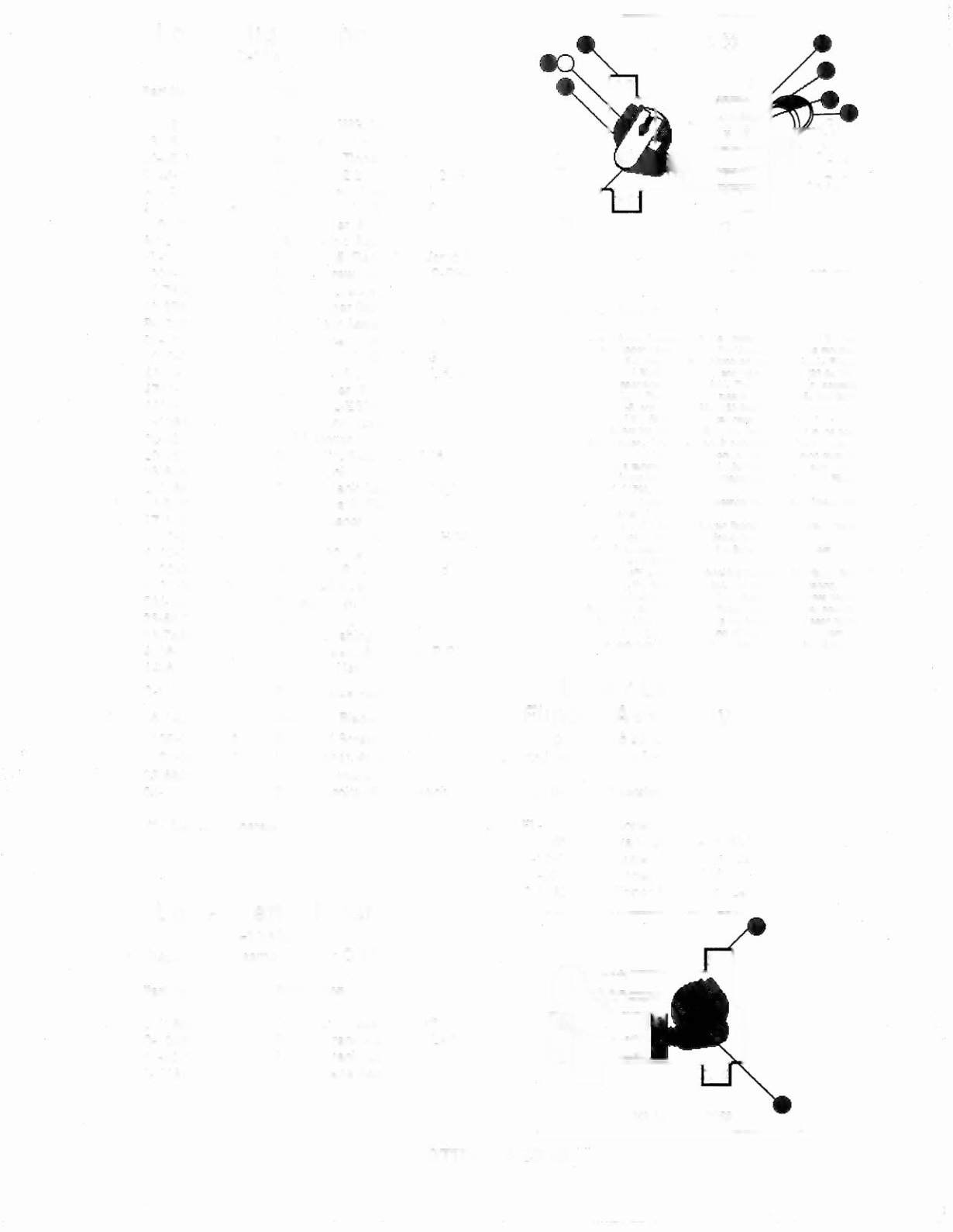
LOWER RIGIIT FLIPPER
Flipper Assembly Notes:
1 Each Flipper Assembly on Ihe Lower Playfleld (and Ihe Iwo
Lower Flipper Assemblies on Ihe Upper Playfleld) Is mounled
beneath the playfleld, In conjuncllon wllh the plasllc Flipper
Paddle and Shaft (20·9250·5) and flipper Rubber (23-6519-4)
on the upper side of the playfleld. The Upper Flipper Assembly
on the Upper Playfleld uses a plasllc Flipper Paddle and Shaft
(C·11927-5) and flipper Rubber (23·6553-4).
2 The lip of the EOS Swllch must travel 0.0150 (+ .010, -",000)
Inch, before the conlac1S fully open, wllh lhe flipper In the aClu-
atad position. The EOS Swllch conlacts musl have a gap of
0.062 (t .015) Inch. Adjustment of Ihe EOS Swllch musl be
made at a minimum distance of 0.25 Inch from the switch body.
3 Flipper Assembly C·II626·L·6 (upper left flipper) uses a Flipper
Call, FL·11722.
4 All moving elemenls of Ihe assembly mUSIoperate freely, with
no evidence of binding.
S The large end of the Call Plunger Spring (llem 12) must fk within
the four lugs
01
the Solenoid Bracket.
6 For coil replacement, remove the Solenoid Bracket (item 11) to
prevent screw damage.
7 Use Loelite™ 242 when reattaching screws to the Flipper Stop
Assembly, the Solenoid Bracket, and the Flipper Bushing.
S When replacing the Bumper Plug (llem 14) to restore proper
flipper operation, readjusl the flipper paddle and shaft position.
9 Solid color blue wire connects to the banded end
01
each diode,
mounted on the connector end of the Flipper Call (Item 9).
Trace color wire connects to the unbanded end
01
the diode.
Upper Left
Flipper Assembly
pIn
C-11626-L-6
(Parts listed replace same Items of
Item Part No.
Description
9 FL-11722
Flipper Coil (Green)
13 B-10655-L Crank Link Assembly, L
g)
B-10657-L Flipper Crank Assy, Left
1) 01-8073-L Flipper Crank, Left
18 C-11627-L Flipper Base Assy, Left
LOWER LEFr FLIPPER
EARTHSHAKER 48