Basic HTML Version


Parts Information
Item Part No.
1
2
3
4
5
6
7
8
9
10
11
12
13
a)
b)
c)
d)
e)
f)
1.)
2.)
3.)
g)
1.)
2.)
3.)
4.)
5.)
6.)
7.)
14
15
16
17
18
HW-30018-6
03-7520-2
20-6516
5045-12098-00
RM-21-06
4010-01066-06
4701-00004-00
A-12111
FL-11630
4006-01017-06
01-7695
10-376
B-10655-R
02-4179
4010-01086-14
4700-00023-00
4701-00004-00
4410-01132-00
A-10656
02-4219
20-9370-1
03-8050-1
B-10657-R
01-8073-R
17-1037
4010-01066-18
4410-01127 -00
4700-00107-00
4701-00004-00
RM-23-06
23-6577
03-7568
4006-01005-06
4406-01117-00
C-11627-R
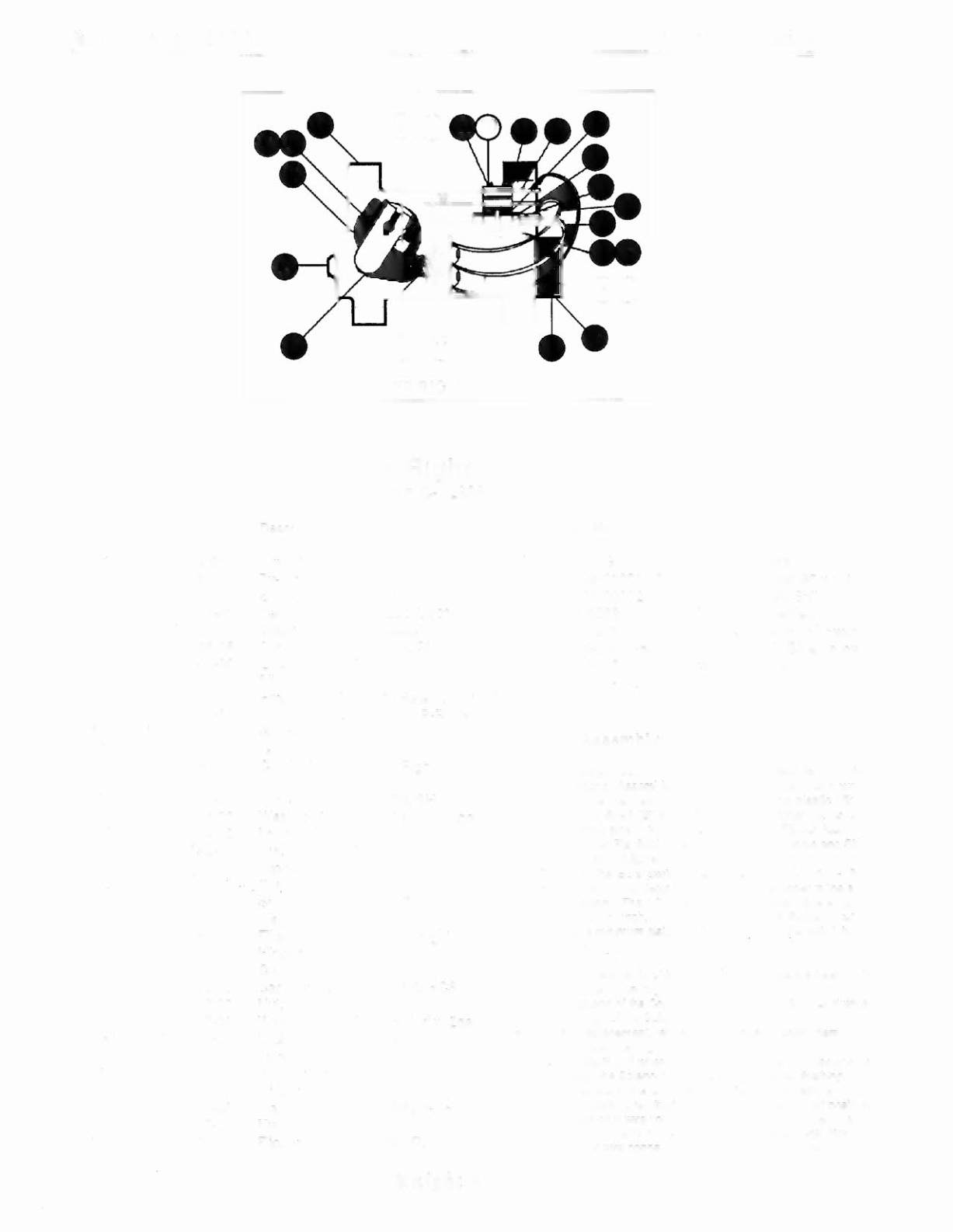
LOWER RIGHT FliPPER
Lower Right Flipper
pIn
C-12898
Description
Wire, 18 AWG, Blue
Ty-Wrap, Nylon
Speednut, Tinnerman
Capacitor, 2.2 ).I.Fd,250V, 20%
Sleeve, Vinyl (Cap. leads)
Cap Screw, 10-32 x 3/8, SH
Lockwasher, #10 Split
Flipper Stop Assembly
Flipper Coil (Red), (* - Refer to Note 3)
Mach. Screw, 6-32
x
3/8, P-RH-S
Solenoid Bracket
Coil Plunger Spring
Crank Link Assembly, Right
Link Spacer Bushing
Cap Screw, 10-32
x
7/8, SH
Washer, 5/8 0.d.x13/64 i. d.x16ga.
Lockwasher, #10 Split
Nut, 10-32 ESNA
Flipper Link Assembly
Coil Plunger
Spring Pin, 5/32 dia. x
7/16
Flipper Link
Flipper Crank Assembly, Right
Flipper Crank, Right
Crank Washer
Cap Screw, 10-32
x
1-1/8, HCS
Nut, 10-32 Hex Hd.
Washer, 5/8 0.d.x13/64 i. d.x12ga.
Lockwasher, #10 Split
Tubing, H. S. 1/4 DWP
Bumper Plug
Flipper Bushing
Mach. Screw, 6-32 x 3/8, P-PH
Nut, 6-32 Hex
Flipper Base Assembly, R.
Jllick
1nt.Q'bt
48
Item Part No.
Description
19 06-14G
Insulating Blade
20 4105-01001-20
Sh. Metal Screw, #5 x 1-1/4
21 4701-00002-00
Lockwasher, #6 Split
22 23-6622
Tape, Double-sided
23 03-7811
End of Stroke (EOS) Switch
24 HW-30018-64
Wire, 18 AWG, BluelYellow
25 01-3670
Switch Plate-Curve
26
SW-1A-183
Flipper Switch
Flipper Assembly Notes:
Each Flipper Assembly on the Lower Playfield (and the two
Lower Flipper Assemblies on the Upper Playfield) is mounted
beneath the playlield, in conjunction with the plastic Flipper
Paddle and Shaft (20-9250-5) and flipper Rubber (23-6519-4)
on the upper side of the playfield. The Upper Flipper Assembly
on the Upper Playfield uses a plastic Flipper Paddle and Shalt
(C-11927-5) and nipper Rubber (23-6553-4).
2 The tip of the EOS Switch must travel 0.0150
(+
.010, - .000)
inch, before the contacts fully open, with the llipper in the actu- .
ated position. The EOS Switch contacts must have a gap of
0.062 (± .015) inch. Adjustment of the EOS Switch must be
made at a minimum distance
01
0.25 inch from the switch body.
3 Not Used.
4 All moving elements of the assembly must operate Ireely, with
no evidence
01
binding.
5 The large end of the Coil Plunger Spring (item 12) must fit within
the four lugs of the Solenoid Bracket.
6 For coil replacement, remove the Solenoid Bracket (item 11) to
prevent screw damage.
7 Use Loctile'" 242 when reattaching screws
10
the Flipper Stop
Assembly, the Solenoid Bracket, and the Flipper Bushing.
8 When replacing the Bumper Plug (item 14) to restore proper
Hipper operation, readjust the flipper paddle and shalt position.
9 Solid color blue wire connects to the banded end
01
each diode,
mounted on the connector end
01
the Flipper Coil (item 9).
Trace color wire connects to the unbanded end of the diode.