Basic HTML Version


pIn
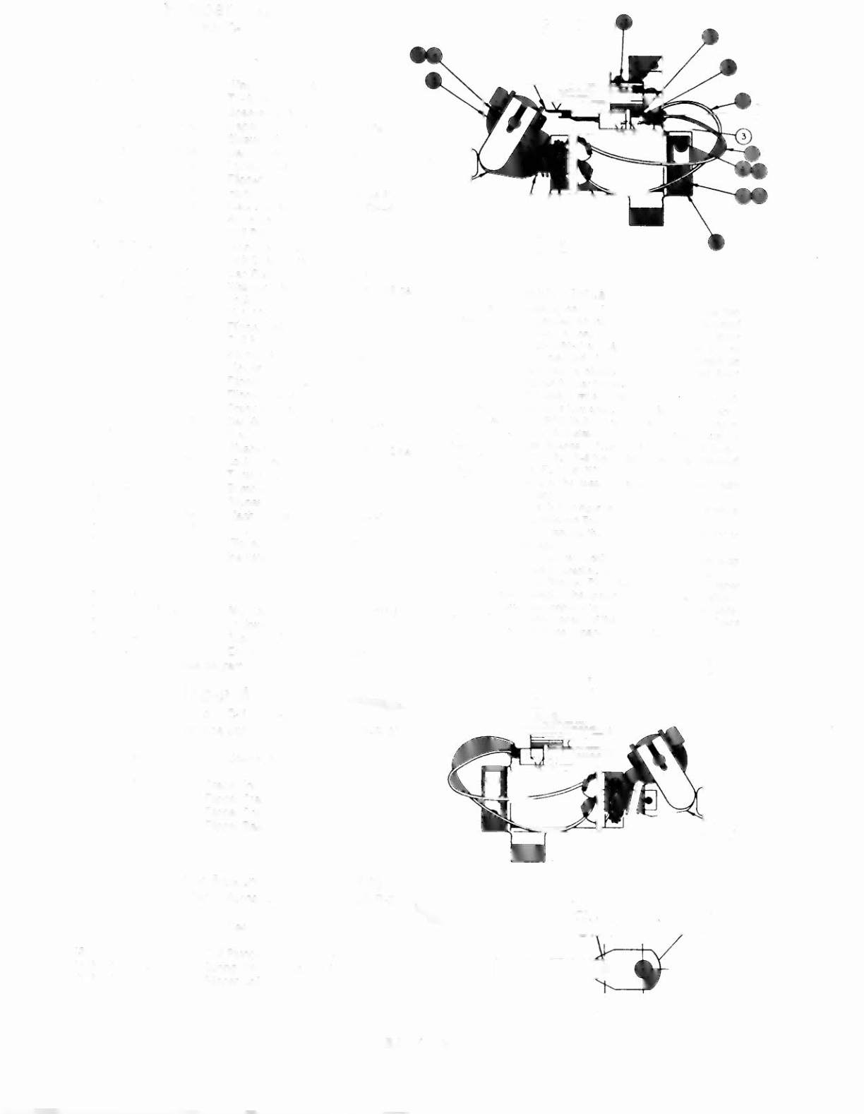
C-11626-R-3
Item Part No.
Description
1 HW-30018-6
2 03-7520-2
3 20-6516
4 5045-12098-00
5 RM-21-06
6 4010-01066-06
7 4701-00004-00
8 A-12111
9 FL-11630/5OV*
10 4006-01017-04
11 01-7695
12 10-404
13 B-l0655-R
a) 02-4179
b) 4010-01086-14
c) 4700-00023-00
cI)
4701-00004-00
e) 4410-01132-00
o
A-l0656**
1.) 02-4219
2.) 20-9370-1
3.) 03-8050-1
g) B-l0657-R
1.) 01-8073-R
2.) 17-1037
3.) 4010-01066-18
4.) 4410-01127-00
5.) 4700-00107-00
6.) 4701-00004-00
7.) RM-23-06
14 23-6577
15 03-7568
16 4006-01005-06
17 4406-01117-00
18 C-11627-R
19 06-14G
20 Not Used
21 Not Used
22 Not Used
23 4105-01019-10
Sh. Metal Screw, #5 x 5/8, P-PH-A
24 4701-00002-00
Lockwasher, #6 split
25 23-6622
Tape, Double-sided
26 03-7811
End of Stroke (EOS) Switch
** - also see separatediagram
Wire, 18 AWG, Blue
Ty-Wrap, Nylon
Speednut, linnerman
Capacitor, 2.2 IlFd, 25OV,20%
Sleeve, Vinyl (Cap. leads)
Cap Screw, 10-32 x
3/8,
SH
Lockwasher, #10 split
Flipper Stop Assembly
Ripper Coil
(* - Refer to Note 3)
Mach. Screw, 6-32 x 1/4, P-RH-S
Solenoid Bracket
Coil Plunger Spring
Crank Link Assembly
Link Spacer Bushing
Cap Screw, 10-32 x
7/8,
SH
Washer,
5/8
o.d. x 13/64 i. d. x 16 gao
Lockwasher, #10 split
Nut, 10-32 ESNA
Flipper Link Assembly
Coil Plunger
Spring Pin, 5/32 dia. x
7/16
Flipper Link
Flipper Crank Assembly, Right
Flfpper Crank, Right
Crank Washer
Cap Screw, 10-32 x
1-1/8,
HCS
Nut, 10-32 Hex Hd.
Washer,
5/8
o.d. x 13/64 i. d. x 12 gao
Lockwasher, #10 split
Tubing, H. S.
1/4
DWP
Bumper Plug
Flipper Bushing
Mach. Screw, 6-32 x 3/8, P-PH
Nut, 6-32 Hex
Flipper Base Assembly, R.
Insulating Blade
Flipper Assembly _ ••..
pIn
C-11626-L-3
(Parts listed replace same Items of C-11626-R-3)
Item
Part No.
Description
13 B-10655-L
g) B-10657-L
1.) 01-8073-L
18 C-11627-L
20 Not Used
21 Not Used
Crank Link Assembly
Flipper Crank Assembly, Left
Flipper Crank, Left
Flipper Base Assy, L.
Flipper Link Assembly,
pin
A-10656
(Items listed refer to items listed for C-11626-R-3)
Item Part No.
Description
13 f) 1.) 02-4219
13 f) 2.) 20-9370-1
13 f) 3.) 03-8050-1
Coil Plunger
Spring Pin,
5132
dia. x 7/16
Flipper Link
8
Flipper Assembly Notes
1 Each Flipper Assembly on the Lower Playfield (and the two
Lower Flipper Assemblies on the Upper Playfield) is mounted
beneath the playfield, in conjunction with the plastic Flipper
Paddle and Shah (20-9250-6) and flipper Ribber (23-6519-4) on
the upper side of the playfield. The Upper Ripper Assembly on
the Upper Playfield uses a plastic Flipper Paddle and Shaft
(20-9264-6) and flipper Ribber (23-6553-4).
2 The tip of the EOS Switch must travel 0.0150 (+ .010, _ .000)
inch, before the contacts fully open, with the flipper in the actu-
ated position. The EOS Switch contacts must have a gap of
0.062 (± .015) inch. Adjustment of the EOS Switch must be
made at a minimum distance of 0.25 inch from the swnch body.
3 Flipper Assembly C-II626-R.a (upper flipper on Lower Playfield)
uses a Ripper Coil, FL-11753150V.
4 All moving elements of the assembly must operate freely, wnh
no evidence of binding.
5 The large end of the Coil Plunger Spring (item 12) must fit w~hin
the four lugs of the Solenoid Bracket.
6 For coil replacement, remove the Solenoid Bracket (item 11) to
prevent screw damage.
7 Use Loctite'" 242 when reattaching screws to the Ripper Stop
Assembly, the Solenoid Bracket, and the Ripper Bushing.
S When replacing the Bumper Plug (item 14) to restore proper
flipper operation, readjust the flipper paddle and shah position.
9 Solid color blue wire connects to the banded end of each diode,
mounted on the connector end of the Ripper Coil (item 9). Trace
color wire connects to the unbanded end 01 the diode.
'.