Basic HTML Version


2.0 Static and Dynamic Convergence
NOTE: Static convergence is achieved by four
magnets located on the neck, nearest the base of the
picture tube, Fig. 2. The middle pair of magnetic rings
are adjusted to converge the blue and red crosshatch
lines. The rear pair of convergence rings (closest to
the base of the picture tube) are adjusted to converge
the magenta (blue/red) to the
green
crosshatch lines.
Dynamic convergence is achieved by tilting the
deflection yoke up-down and left-right.
2.1 Ensure that the controls misadjusted during purity
setup (screen, cut-off, etc.) are set to give white
balance. See 3.0 below.
2.2 Switch generator to the crosshatch pattern.
2.3 Adjust convergence around the edges of the picture
tube by tilting the yoke up-down and left-right, and
temporarily install one wedge at the top of the yoke or
in a more optimum position. (Figures 8, 9,
10)
2.4 Turn off green input and turn on the red and blue
input.
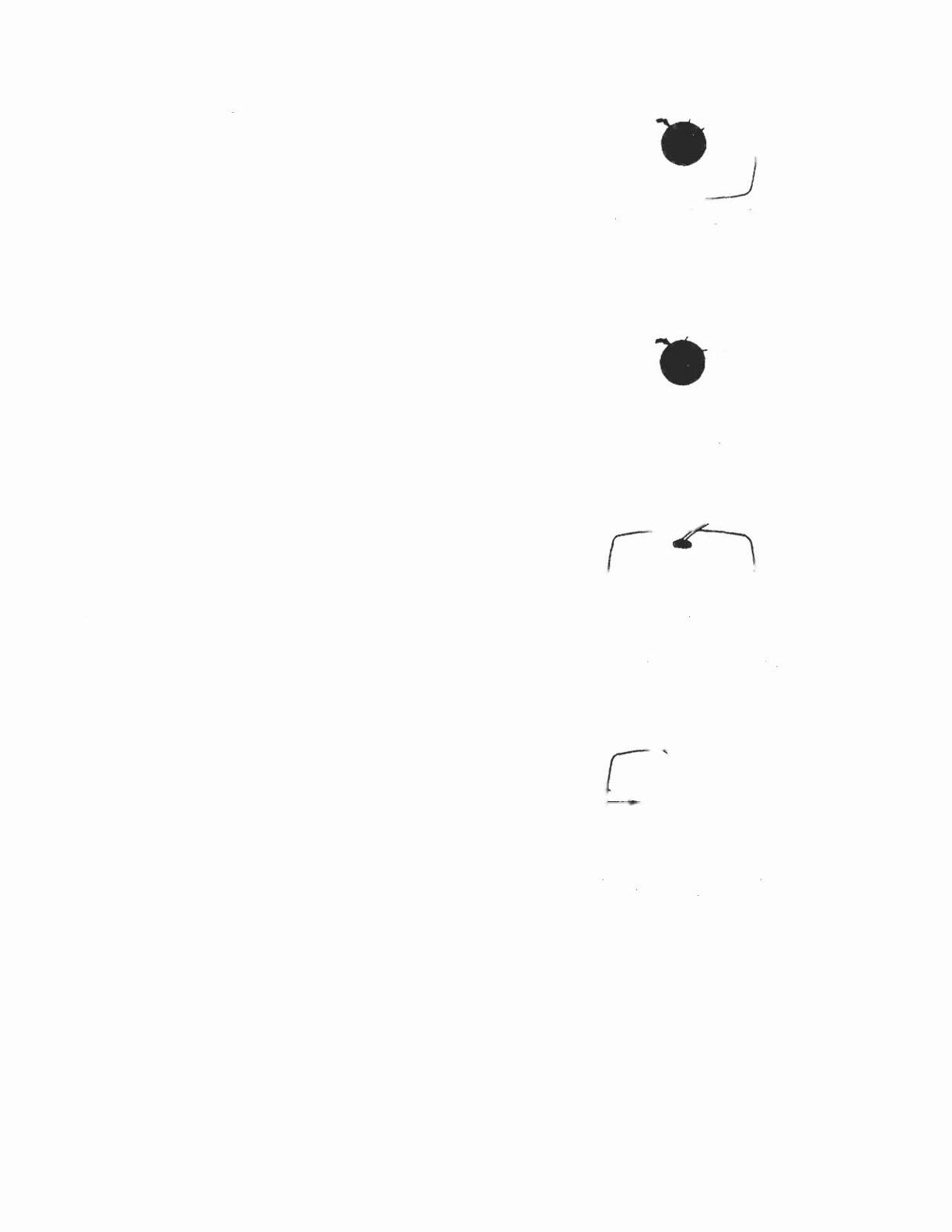
2.5 Rotate the 4-pole (middle) pair of magnets as a unit to
minimize separation of the red and blue crosshatch
lines around the center of the screen (Figure 6). Varia-
tion of the angle between the tabs adjusts convergence
of red and blue. (Tilt yoke as required to converge red
and blue at the edges as in 2.3 above.)
2.6 Turn on green input to obtain magenta (red/blue) and
green crosshatch lines. Rotate the 6-pole (rear) pair of
magnets as a unit to minimize separation of the
magenta and green lines (figure 7). Vary angle
between the two tabs and further rotate as a unit to
finalize.
2.7 When converence of 3 colors is optimized (static in
center and dynamic around edges) apply stripe of
paint or nail polish to converence magnet rings to
prevent movement. If applicable, tighten locking ring
carefully.
2.8 Remove temporary wedge from yoke. Tilt yoke in up-
down and left-right direction for best circumference
convergence and install 3 wedges. (It is best to use 3
new wedges since they have adhesive backing. Simply
pull off tape, slide wedge in place and press outer flap
down firmly. For more permanency apply small
quantity of silastic or similar material at junction of
wedges and picture tube. Do not disturb while material
is setting. (Order wedges by part number.39-1233-01).
3.0 White Balance (Grey Scale Tracking)
Refer to figure 3. Do the following in subdued light:
3.1 Note this adjustment can be accomplished with no
signal connected; eg: input connector open or if a
signal generator is connected. switch off all 3 inputs at
the generator.
3.2 Set red and green drive controls to their mechanical
center and turn the common G2 screen control and 3
cut-off controls to minimum (fully counterclockwise).
3.3 Slowly turn up G2 screen control until the first faint
color appears. then back off to edge of visibility. Do
not touch the associated cut-off control- it should stay
fully CCW for the remaining set-up.
3.4 Slowly turn up the other two color cut-off controls in
turn to match the first. This should result in the faintest
grey.
3.5 Turn on the signal generator with all 3 inputs on. (a
crosshatch pattern would be appropriate).
[FRONT VIEW!
r
"'
Around~
cOn,ro
W
9'uo
'------
L.t the r«J and blue
linel
come
In
lin. by
turning two 4-pOl.
ml9nen.
Figure 6
[FRONT VIEW]
Green
ArOUnd-e
centre _
Magenta
.
-
, -'
Let the green and magent.
!lnu come .n. line
bV
turning two
6-pole magn.".
Figure 7
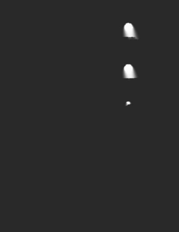
[REAR VIEW]
Roughly &d,u",
tnl clrcumf.ren.tl,1
con-
••..ergence and install one wedge temporarily.
Figure 8
[FRONT VIEW)
R~ Gr~n ~~e
r
,
,\
/"
Blue-
"~
';
Red
Gr •• n-
'"
~;
·Gre,n
/~
--
Red-
,,'--
-8' •••
\._ "/
,I
.J
,
,
Blue
Gr~
Red
Tilting the yoke upward will move 1he
Ii,...,
Figure 9
IS
shOwn with 1he arrowt.
Tilting I •..••yoke 10 Ihe ught
'Nil I
move
,n_
llnei II
,t'Iown 'NIt"
tn,
arrO'N'
Figure 10