Basic HTML Version


C-9953-L
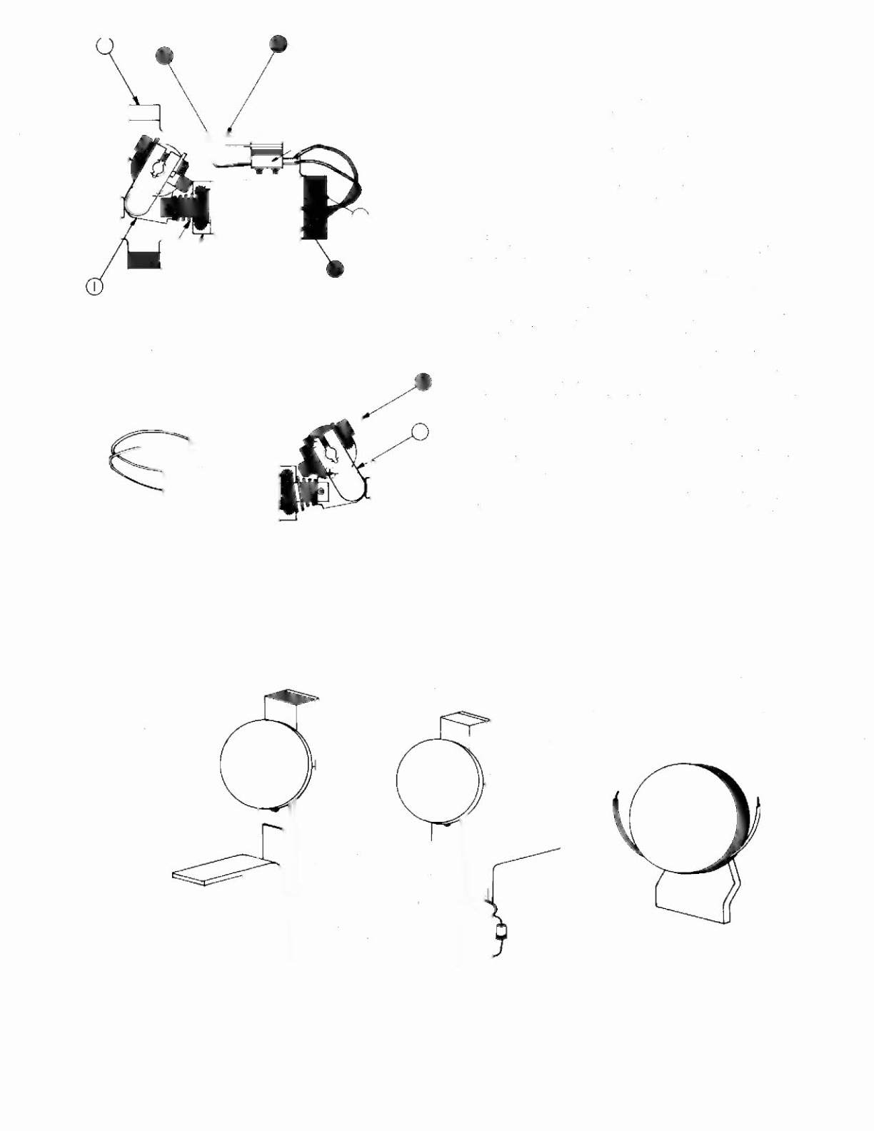
ITEM PART NO.
DESCRIPTION
Flipper, Unique Parts
1
2
S·10655·l
C·9957·l
Cran k link Assembly. left
Flipper Sub Base Assembly
A-92G8
C-9952-R
ITEM PART NO.
1
2
20
2b
2c
2d
3
4
5
6
B·10655·R
C·9954·R
03·7811
5W·1A·150
03·7568
A·10280
01·7695
10·376
FL231600·3012600
23·6577
Flipper
DESCRIPTION
Crank link Assembly
flipper Base/Lane Change ASSembly
End of Stroke (EOSJSwitch
lane Change Switch
Flipper Bushing
Flipper Stock Bracket Assembly
Solenoid Brocket
Coil Plunger Spring
Flipper COil
Bumper Plug
NOTES
1 Each Flipper Assembly is mounted below the ciovneio in con-
Junction with the plastic nipper and shaft (20·9250) and flipper
rubber (23·6519) (on the upper side or the playrield)
2 The tip of the EOS Switch must travel
.015 1+.010. . 000 incnj,
before the contacts fully open with the flipper in the actuated
position.
The EOS Switch contacts must have a gop of .062
I.!.
.015J Inch. Any adjustment of the EOS SWitch must be made ot
a minimum distance of .25 inch from the switch body
3 The lane Change Switch must have a gap of .046 (~ 015] inch.
when fully open
4 All moving elemenls of the assembly must operate freely witnout
any evidence of binding
5 Coil plunger spring must fit within the four lugs or the sotenoro
bracket
6 For Call replacement,
remove solenoid brocket. (item 3J to pre-
vent screw damage
Use loctite when reassembling flipper stop brocket screws.
8 When USing bumper plug on Older flipper assemblies.
readjust
flipper position
9 Solid color grey (or blue] wire connects to the banded end of the
diode. mounted on the connector end of rlipper coil (item 5J Wire
with trace color connects to the un bonded end or the diode
2
A-9270
Grand Lizard Standup Targets
&
GRAND LIZARD 39
o
A-8447
Magna-Save™