Basic HTML Version


486
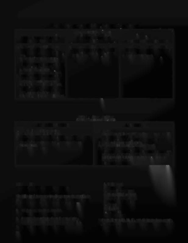
Table
13.
No Response to CPU Self-Test or Intermittent Operation
I
LEDs DO NOT FLASH AND
I
REMAIN OFF WHEN
LEDs REMAIN ON AFTER
DIAGNOSTIC SWITCH
POWER TURN-ON
DEPRESSED
INTERMITTENT OPERATION
1. Check +5 VDC and Unregulated
1. Turn game OFF and back ON.
1. Make checks described in step 1
Logic B+ on CPU and Power
2. If problems persist, check +5 VDC
for LEDs remaining on after power
Supply Boards. (See Table 4.) If
from power supply. If ok, replace
turn-on.
low:
CPU Board.
2. Replace CPU Board.
a. Check ac input from trans-
former,
b. Check wiring from
transformer .
to 3PI-IO, -11, and -12.
c. Check 3D6 and 3D?
d. Replace Power Supply Board.
2. Turn game OFF and completely
remove Driver Board from the
backbox. Reapply power and
depress the DIAGNOSTIC push-
button on the CPU Board. If the
LEDs blink twice and then remain
OFF, replace the Driver Board.
Otherwise. replace the CPU Board.
Table 14. Sound Problems
(Place Diagnostics in Test 02)
I OR MORE SOUNDS
ALL SOUNDS
I. Broken wire to 1013 connector.
Never Sound.
2. Replace ROM on Sound Board.
I. Check fuses IOFI and IOF2 on Sound Board and ?F2
3. Open driver on Driver Board; replace driver on Driver
adjacent to Sound Board.
Board.
2. Check connectors 10JI, IOJ2, 1013 and IOJ4.
4. Open Buffer on Sound Board; replace buffer on
3. Check volume control position.
Sound Board.
4. Check amplifier portion of Sound Board.
5. Replace Sound Board
5. Replace ROM on Sound Board.
6. Remove connector 101'3 and momentarily ground one
of the used input pins of 1013.
1£
a sound is produced.
a solenoid driver transistor is stuck on, Repair or
replace Driver Board.
7. Replace Sound Board.
..
SECTION 7
INTERCONNECTION CHARTS
I. CPU Board
2. Driver Board
3. Power Supply Board
4. Master Display Board
5. Slave Display Board
6. Back Box Miscellaneous
7. Cabinet
8. Playfield
9. Insert Rox
10. Sound Board
Refer to Figures 10, ll, 12, and 13 for the lamp matrix,
switch matrix, solenoid matrix, and connector identifica-
tion; respectively.
The following interconnection charts are used to identify the
color and pin number of all the wires for all the components.
The following conventions are used throughout-
I.
IJ 1 is connector J I on board
I.
3J6 is connector J6 on board 3.
2.
J designations refer to the male part of plug.
P designations refer to the female part of plug.
3. The Prefix numbers are as foliows:
26