Basic HTML Version


2. To service motor
a. De-solder motor wire leads, noting which color wire belongs to which terminal.
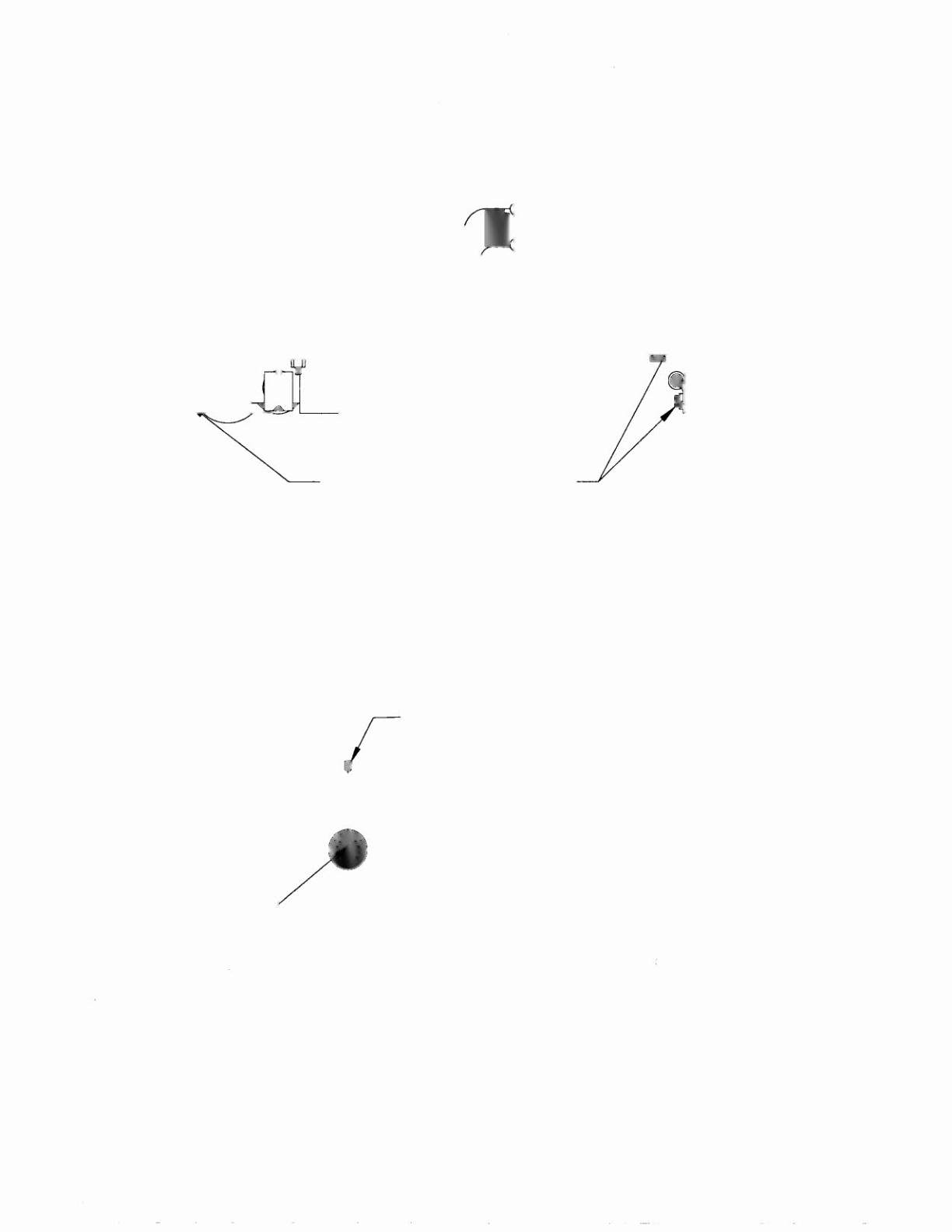
b. Remove four (4) motor mounting screws. Motor can now be removed. (See Fig. 6)
4 MOTOR MOUNTING SCREWS
(2 PER SIDE)
Fig. 6
c. If replacing motor, be sure to remove pinion gear from the motor shaft and install it on the new
motor shaft. (See Fig. 7) Apply Loctite to set-screw and use a .050 Hex Allen wrench to re-
install. Do not over tighten, screw may strip.
REMOVE SET SCREW
r
AND
SLIDE PINION
7
GEAR OFF OF MOTOR
I
I
I
I
I
I
I
I
I
I
I
SET SCREW MUST BE
SEATED AND SECURED
ON THE FLAT OF THE
MOTOR SHAFT
o
o
o
o
SLIDE PINION GEAR
THIS DIRECTION
o
Fig. 7
d. Re-install new motor, making sure that there is proper engagement between the rack and
pinion.
e. Solder wire leads back onto terminals.
1-59