Basic HTML Version


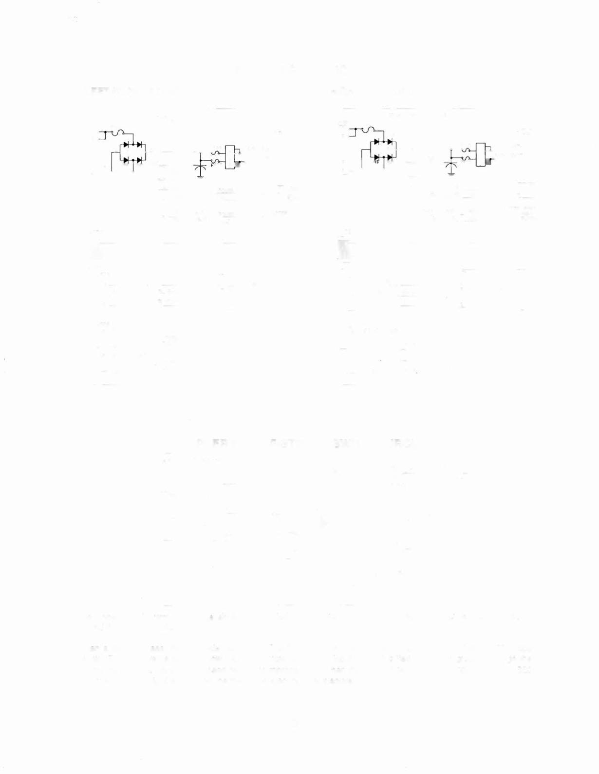
FLIPPER COIL CIRCUITS
LEFT FLIPPER CIRCUIT
RIGHT FLIPPER CIRCUIT
POWER DRIVER BOARD
POWER DRIVER BOARD
J128
PLAYFIELD
LOWER
LEFT
1--------""'-=--+--+-+--'
FLIPPER
YELLOW-GREEN
~?tH~R
I-"'0R~A",NG",E__;-G""R",EE"-,-N--,H",O",,LO'---t-_-I-+---__j
FLIPPER
ORANGE-VIOLET HaLO
YELLOW -VIOLET POWER
Jl02
Jl02
CPU BOARD
CPU BOARD
GROUND ORANGE
:
~6
RIGHT CABINET
I-F2_c::LO,,-W_;:E:__R_+-BL_U_E -_V_IO_LE_T-j~ ~ OPTO BOARD
F6 UPPER BLACK-YELLOW ~ ~
J1
GROUND ORANGE
6
W
7 LEFT CABINET
F4 LOWER BLUE-GRAY
3 OPTO BOARD
I-FB~U"-PP_;:E:__R-I-B-LA-C-K---BL-U-jE
i
2 J1
J211
J212
J211
J212
uPPER LEFT
E.O.S. SWITCH
LOWER RIGHT
E.O.S. SWITCH
LOWER LEFT
~="-=--_+ -'
E.O.S. SWITCH
UPPER RIGHT
E.O.S. SWITCH
FLIPPER END-OF-STROKE SWITCH CIRCUIT
1---- - - -- - - - -- - - - --1
I
Dedicated Inpu t
I
+5V r+ 12V
I
~
~
I
I
1K
I
I
I
1
1---:-1
___:B::.::LA:..;.C::....K.c__-_:_X-,,-X"ox
I
1
I
1
I
1
1
CPU BOARD
I
I
I
1
L
~
SWITCH
OPEN
CLOSED
ORANGE
PLAYFIELD
The flipper E.O.S. circuits operate similar to the dedicated switch circuit. The circuits are active low and tied to
ground through the switch.
When a switch closes, the row side, (dedicated input), of the circuit activates. The "+" input of the LM339 drops
below +5V therefore its output is low. Since the row (dedicated input), circuit is tied directly to ground through the
switch, the switch is considered closed by the microprocessor. When the switch
opens, the "+" input to the
LM339
is above +5V, its output is high and the row (dedicated input) is inactive.
3-12