Basic HTML Version


LAMP MATRIX
Yellow(B+) ~Red
~
1
2
3
4
5
6
7
8
Yellow-
Yellow-
Yellow-
Yellow-
Yellow-
Yellow-
Yellow-
Yellow-
Brown
Red
Orange
Black
Green
Blue
Violet
Gray
J121-1
J121-2
J121-3
J121-4
J121-S
J121-6
J121-7
J121-9
w
096
0100
095
099
094
098
093
097
1
Red-
JEWEL
JACKPOT
MAGIC
SMOKE
SMOKE
MAKE A
ACTION
EXTRA
Brown
1
CARPET
6
14
WISH
2
BALL
J12S-10104
(LEFT)
(TOP)
11
21
31
41
51
61
71
81
2
Red-
JEWEL
(G)ENIE
ACTION
SMOKE
LAMP-1S (B)AZAAR
LEFT
ACTION
Black
2
3
7
LOCK
5
J12S-20108
12
22
32
42
52
62
72
82
3
Red-
JEWEL
G(E)NIE
RAMP
SMOKE
LAMP-30
B(A)ZAAR
HAREM
RIGHT
Orange
3
ARROW
8
ADVANCE
LOCK
J12S-40103
RIGHT
13
23
33
43
53
63
73
83
4
Red-
JEWEL
GE(N)IE
RAMP
SMOKE
LAMP-60
BA(Z)AAR LEFT TIGER RIGHT
Yellow
4
ARROW
9
LOOP
TIGER
J12S-S0107
LEFT
LOOP
14
24
34
44
54
64
74
84
5
Red-
JEWEL
GEN(I)E
SMOKE
SMOKE
SMOKE
BAZ(A)AR ACTION
CAPTIVE
Green
S
1
10
4
1
BALL
J12S-60102
(BOTTOM)
RIGHT
15
25
35
45
55
65
75
85
6
Red-
JEWEL
GENI(E)
SMOKE
SMOKE
SMOKE
BAZA(A)R
WISH
ACTION
Blue
6
2
11
S
1
4
J12S-70106
16
26
36
46
56
66
76
86
7
Red-
JEWEL
MULTIBALL
SMOKE
SMOKE
SHOOT
BAZAA(R)
WISH
CAPTIVE
Violet
7
3
12
STAR
2
BALL
J12S-80101
(RIGHT)
RIGHT
LEFT
17
27
37
47
57
67
rr
87
8
Red-
SHOOT
OUTLANE
AMULET
SMOKE
SHOOT
CENTER
WISH
START
Gray
AGAIN
SPECIAL
13
STAR
LOCK
3
BUTTON
J12S-9010S
LEFT
18
28
38
48
58
68
78
88
J1XX
=
Power Driver Board
LAMP MATRIX CIRCUIT
:--------------C~I-U-~-~-(~~~-~~I~)-------:;:18v---------------------l
--=-C-"-O=LU=._M,,,-,-,N---t;- '; t - '' -+:::-==-
:
:
OFF
:
:
ON
I
I
:
J1X:
i
x H:_Y_ell_OW_-_xx_x------'<OY---t.r-,
I
I
I
I
I
I
I
I
I
J1XX I
I
I
:
H'~R~ed~- x~x
~
I
I
I
I
I
I
I
I
I
I
I
I
I
I
I
I
I
L
~
PLAYFIELD
ROW
NORMAL
H
OPERATION H
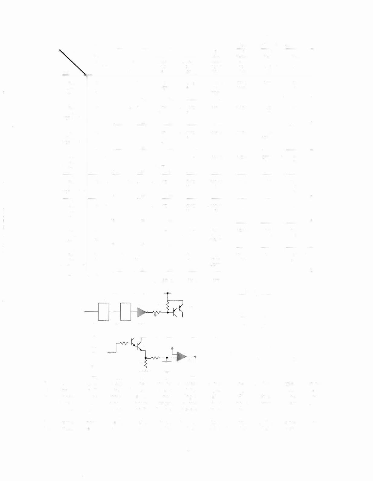
The microprocessor sends a signal to the column circuit causing the output of the UNL-2803 to toggle. When point
"A" drops low, the TIP107 transistor conducts and point "B" changes to a high state. At the same time, the
microprocessor drives the input of the 74LS74 low, causing a high at output "F". A high state at the base of the
TIP102 causes the transistor to conducts, bringing the row circuit to ground and turning the lamp on. The
microprocessor changes the input of the 74LS74 to a high state to turn the lamp off.
In overcurrent conditions, the lamp is shut off through the comparator. If the voltage at the negative input of the
LM339 rises above 1.4V, the output changes to a low, which is fed back to the 74LS74 and shuts the circuit off.
3-4