Basic HTML Version


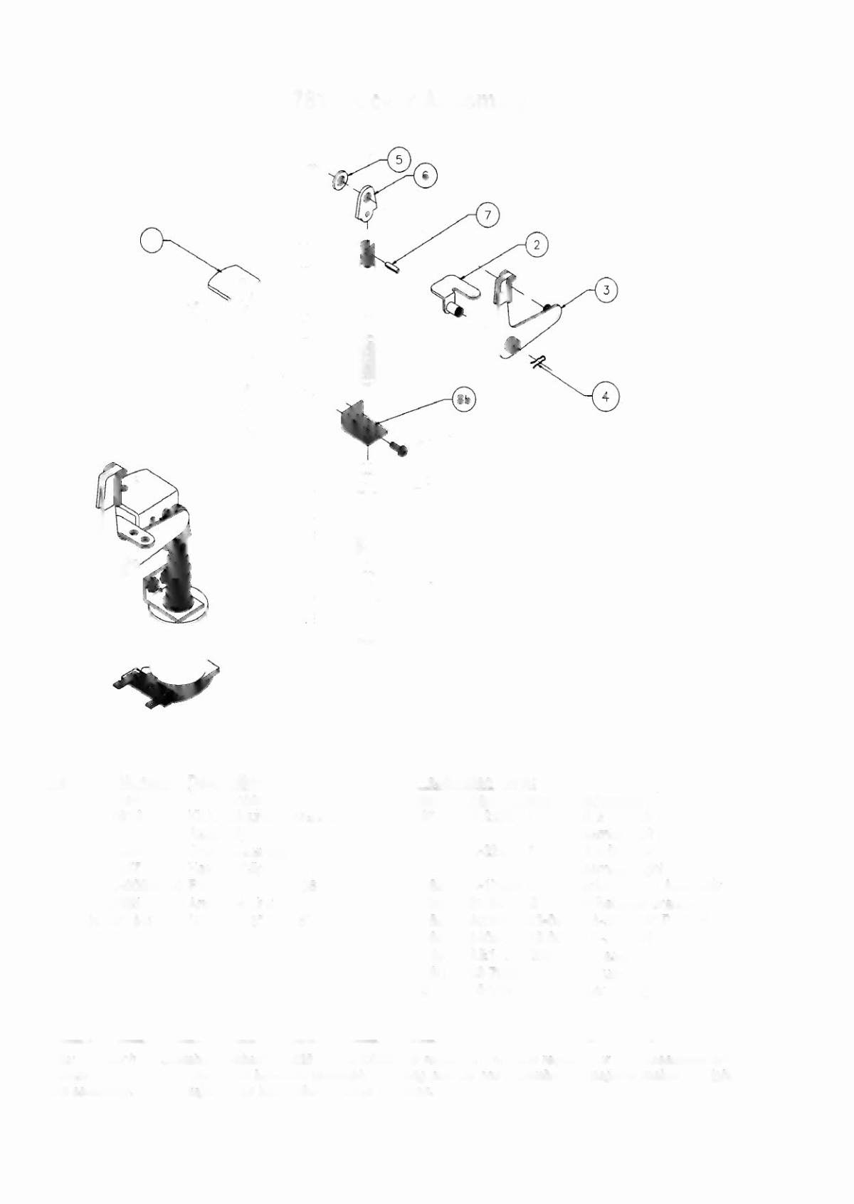

A·17811 Kicker Assembly
Hem Part Number Description
1
02-2364
Coil Plunger
2
A-17810
Kicker Mounting Bracket
Assembly
3
A-l2664
Crank Assembly
4
12-6227
Hair Pin Clip
5 47CJO.OC1O»OOFW
.265 x .500 x .067
6
03-8085
Armature Unk
7
20-8716-5
Roll Pin
1/8"
x
7/16"
Associated Parts:
Hem Part Number
8*
A-'J2207-7
88)
8b)
8c)
8d)
8e)
8f)
9
Description
Coil
&
Bracket
Assembly-Left
Coil
&
Bracket
Assembly-Right
A-17808
Bracket
&
Stop Assembly
01-8-508-S
Coil Retainer Bracket
4006-01003-06
MS 6-32 x 3/8" P-PH-S
4406-01119-00
Nut 6-32 ESN
AEl-27-1200
Coil Assembly
03-7066
Coil Tubing
10-128
K~erSpring
A·'J2206-7
*Note:
One
each
of
assembly
numbels
A-22207-6
and
22206-618 required.
The
parts required
for
both assemblies
are
identical. The
IlIusITatlon
shows the left-hand
assembly.
Rotating pan
Be,
coil assembly, 180degrees makes the right-
hand
ass«nb/y.
The
coil lugs
will be
facing
the opposite
direction.
2-16