Basic HTML Version


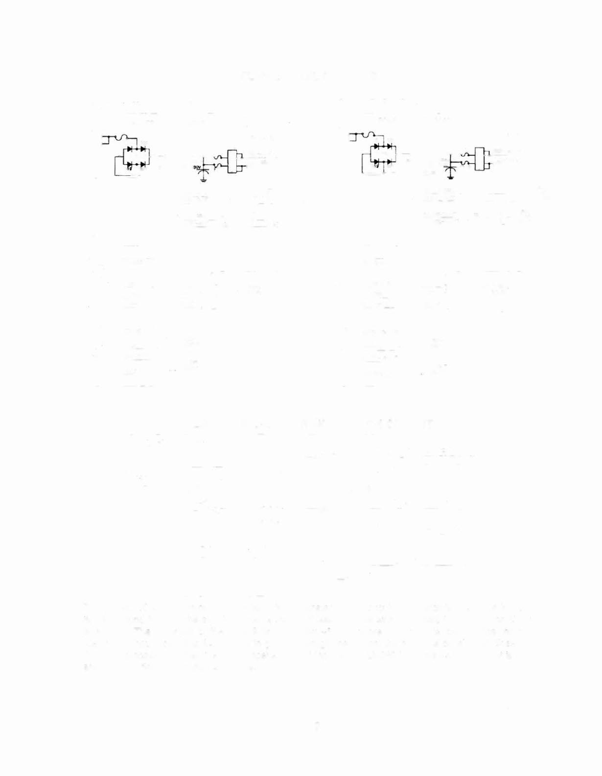

fLIPPER COIL CIRCUITS
LEFT FLIPPER CIRCUIT
RIGfH FLIPPER CIRCUIT
POWER DRIVER BOARD
POWER DRIVER BOARD
LOWER
LEFT
I-'-_ .:.::__: _--- -'----'~_
_+__+_-+----,
'-UPPER
JI02
JI02
ORANGE
GROUND ORmGE
:~'
RIGHT CABINET
r2 LOWER BLUE -VIOLET
~
~
OPTO BOARD
~_;C::S=",-U::::.~P.;;..E:;;'R~~:::..:B-LAC:;...;K~--Y;..::E~LL~OW~
? ;
J
1
' -- ----- - '
CROU~D
CPU BOARO
CPU BOARO
J211
J212
6 I ~7
un
C~BINEl
••
LOWER
BLUE -GRAY
;
OPIO BOARD
~~~~-~~~~
1
rs
UPPER
BLACk -
9LU£
2 J1
UPPER
LEFT
r.o.s,
SWITCH
LOW£R RIGHT
COS SWITCH
LOWER
LEFT
rr=""---t-'
E.O.S.
SWITCH
UPPER RICHT
E.O.S. SWITCH
fLIPPER END-Of-STROKE SWITCH CIRCUIT
,- -
----------
----,
Jed icated Input
I
I
+5V
+12V
:
lKr:
I
I
I
I
I
I
I
470
p
fT
I
I
:
CPU BOARD
J.!:
ORA'GE
I
_L
~_II--__:::..c~"-,,-=-
·-,
I
I
L
~
OP~N H H
SWITCH A
B
CLOSED L L
BLACK-XXX
PLAYFIEL.D
The flipper E.O.S. Circuitsoperate similar to the dedicated switch circuit. The circuits are active
low and
tied to ground through the switch. When a switch closes, the row side, (dedicated input), of the circuit
activates.
The "+" input of the LM339 drops below +5V therefore its output is low. Since the row
(dedicated input), circuit is tied directly to ground through the switch, the switch is considered closed by
the microprocessor. When the switch opens, the
"+"
input to the LM339 is above +5V, its output is high
and the row (dedicated input) is inactive.
3-12