Basic HTML Version


TEST/DIAGNOSTIC PROCEDURES
(Continued)
~oa~ 1tngs
Solenoid Table
Sol.
Wire
1
Connections
Driver
Solenoid
Solenoid
No.
Function
Color
CPU Bd.
Playfield/
Trans.
Part No.
Type
Cabinet
01 Outhole
Controlled Gry-Bm 1Pll-l
8P3-1
Q33
AE-23-800-01
02 Ball Trough Feeder
Controlled Gry-Red 1PII-3
8P3-2
Q25
AE-23-800-03
03 Left Eject Hole Controlled Controlled Gry-Om 1PII-4
8P3-3
Q32
AE-23-800-03
04 Center Eject Hole
Controlled
Gry-Yel
1PII-5
8P3-4
Q24
AE-23-800-03
05A 3 Rear Playfield Flashers
Switched {ViO-Grn } 1Pll-S 8P3-5 (to B4 on
Q31
#S3 flash lamps
05C
3
Upper Left Kicker
Switched
BIk-Gm (Brn-Grn) Diode Sw. Bd.)
Q31 AE-23-800-11 & Relay/Snb
OS Power Kicker (Left Outiane)
Controlled
Gry-Blu 1P11-7
8P3-S
Q23 AE-24-900-01 & Relay/Snb
07 Left Lightning Bolt
Controlled Gry-Vio 1P11-8
8P3-7
Q30
#S3 flash lamps
08 Right Lightning Bolt
Controlled
Gry-Blk 1PII-9
8P3-8
Q22
#63 flashlamps
09 Left Gate
Controlled
Brn-Blk 1P12-1
8P3-9
Q17
SM 1-35-4000-DC
10 Right Gate
Controlled Brn-Red 1P12-2
8P3-10
Q9
SMI-35-4000-DC
11 General Illumination Relay
Controlled Brn-Orn 1P12-4
3P7-1
QIS
5580-09555-00
12 Solenoid Select Relay
Controlled
Brn-Yel
1P12-5
8P3-12
Q8
5580-09555-00
13A 3 Knocker
Switched {ViO-Wht}
1PI2-S 8P3-13 (to B3 on Q15
AE-23-800-02
13C 3 Ramp Up
Switched
Blk-Wht
(Bm-Gm)
Diode Sw. Bd.)
Q15
AE-24-900-02
14A 3 Mid-Insert Board Flashers
Switched {ViO-BIU}
1P12-7 8P3-14 (to B2 on Q7
#63 flash lamps
14C 3 Ramp Down
Switched
Blk-Blu (Brn-Blu)
Diode Sw. Bd.)
Q7
SM·2S-S00-DC
15A 3 Bikes Flasher (Backbox)
Switched {ViO-Blk}
1P12-8 8P3-15 (to Bl on Q14
#S3 flashlamps
15C 3 Drop Target
Switched
Blk-Vio (Brn-Vio)
Diode Sw. Bd.)
Q14
SA-5-24-750-DC
IS Coin-Lockout Relay
Controlled Brn-Gry 1P12-9
7PI-7,7P2-4
QS
404S03-2 (Coinco pin)
17 Left Kicker
Special #1 Blu-Brn 1P19-7
8P3-17
Q75
AE-23-800-03
18 Right Kicker
Special #2 Blu-Red 1P19-4
8P3-18
Q71
AE-23-800-03
19 Upper Jet Bumper
Special #3 Blu-Orn 1P19-3
8P3-19
Q73
AE-23-800-03
20 Left Jet Bumper
Special #4 Blu-Yel
1PI9-S
8P3-20
Q69
AE-23-800-03
21 Right Jet Bumper
Special #5 Blu-Grn lP19-8
8P3-21
Q77
AE-23-800-03
22 Lower Jet Bumper
Special #6 Blu-Blk 1P19-9
8P3-22
Q79
AE-23-800-03
-
Right Flipper
-
Orn-Vio 1P19-1
7PI-20
-
FL23/S00-30/2S00-50VDC
[Blu-Vio)
[7JI-21,8P3-34)2
-
Left Flipper
-
Om-Gry 1P19-2
7PI-23
-
FL23/S00-30/2S00-50VDC
[Blu-Gry)
[7JI-24,8P3-32)2
~ 1. Wire colors, except flipper Om- Vio and Om-Gry, areground connections
(10
coil terminal with unbandedend of diode). Flipper Om- Vio and
Om-Gry wires connect from CPU Board to flipper switch. 2. Flipper connections shown in bracesare from flipper switch to flipper coil.
3.
"A"
coils are pulsed, when Sol. 12 is de-energized;
"C'
coils arepulsed, with Sol. 12energized. Wire colors in brackets are those from respective A and C
terminals corresponding to the B terminal connection listed for the Diode Switching Board, which controls the device pulsing by Sol. 12.
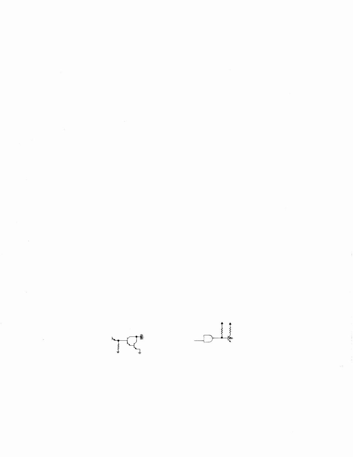
"On" State Logic • Special Solenoid
"On" State Logic· Controlled Solenoid
7407
IJI9 ~34V
~PECIAL
TIP 122 SO~~~\!ID
+5V +5V
+34V
IJ"~ nCONTROLLED
OR
SOLENOID "ON"
IJI2
.r--,.-----,.,
PIA
BLANKING
"Off" State • Special Solenoid:
The Special Switch Trigger Input goes low. Mean-
while, the PIA line remains high. The remaining sig-
nals reverse their states.
"Off" State • Controlled Solenoid:
The Enable Input (from the PIA) goes low. Meanwhile,
the BLANKING signal remains high.
The rest of the
signals reverse their states.
To continuously pulse a single solenoid, use MANUAL-DOWN.
Press ADVANCE to sequence through the
controlled and special solenoids. Use AUTO-UP to resume test cycling, and to proceed to the next test.