Basic HTML Version


Road Kings
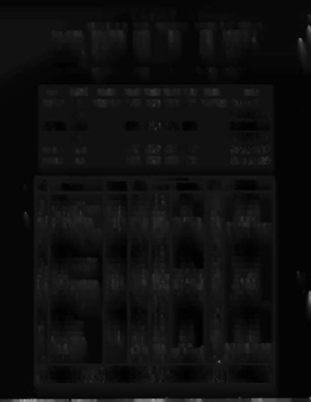
(System-11) ROM Summary
IC
DESCRIPTION TYPE IDENTIFIER BOARD PART NUMBER
Game ROM 1 32K x 8 ROM 27256
U27
CPU A-5343-542-2
Game ROM2
8Kx 8 ROM 2764
U26
CPU A-5343-542-1
Sound ROM 1 32K x 8 ROM 27256
U21
CPU A-5343-542-4
Sound ROM 2 32K x8 ROM 27256
U22
CPU A-5343-542-3
Background
(BIG)
Music ROM 32K x8 ROM 27256
U4
BIG
Music A-5343-542-5
Game
System 11 PIN - U15
PIN - U27 PIN - U26 PIN - U21 PIN - U22 PIN - U24
Jumpers
CPU Rev.
High Speed
A
5400-09250-00 A-5343-
A-5343-
A-5343-
A-5343- 5400-09250-00 W1, 2, 4, 5, and 7
I
541-1
541-5 541-3 541-2
t
B,C,D
~
~
~
~
W1,2,4,5, 7,8,11,12,
13,14,16,17,
and 18
Alley Cats
A
A-5343-
A-5343- A-5343-
A-5343-
W1, 3, 5, and 7
I
1918-2 1918-1 1918-4 1918-3
+
B,C,D
~
~
~ ~
W1,3,5, 7,9,11,12,
13,14,16,17,
and 18
Grand Lizard
B,C,D
A-5343-
A-5343-
A-5343- A-5343-
W1, 2, 4, 5, 7, 8, 11, 12,
523-1
523-5 523-2 523-3
13, 14, 16, 17, and 18
Road Kings
D-G
A-5343-
A-5343-
A-5343- A-5343-
W1,2,4,5,
7,8,11,12,
542-2
542-1 542-4 542-3
13,14,16,17,
and 18
Sol.
Wire
I
Connections
Driver
Solenoid
Solenoid
No.
Function
Color
CPU Bd.
Playfleldl
Trans.
Part No.
Type
Cabinet
01 Outhole
Controlled Gry-Bm 1P11-1
8P3-1
033
AE-23-800-01
02 Ball Trough Feeder
Controlled Gry-Red 1P11-3
8P3-2
025
AE-23-800-03
03 Left Eject Hole Controlled Controlled Gry-Om 1P11-4
8P3-3
032
AE-23-800-03
04 Center Eject Hole
Controlled
Gry-Yel
1P11-5
8P3-4
024
AE-23-800-03
05A
3
Rear PJaylield Flashers
Switched {Via-Grn } 1P11-6 8P3-5 (to 84 on
031
#63 flashlamps
05C
3
Upper Left Kicker
Switched
BIk-Gm (Bm-Gm) Diode Sw. Bd.)
031 AE-23-800-11
&
Relay/Snb
06 Power Kicker (Left Outlane)
Controlled
Gry-Blu 1P11-7
8P3-6
023 AE-24-900-01
&
Relay/Snb
07 Left Lightning Bolt
Controlled
Gry-Vio 1P11-8
8P3-7
030
#63 flashlamps
08 Right Lightning Bolt
Controlled
Gry-Blk 1P11-9
8P3-8
022
#63 flashlamps
09 Left Gate
Controlled
Brn-Blk 1P12-1
8P3-9
017
SM 1-35-4000- DC
10 Right Gate
Controlled Brn-Red 1P12-2
8P3-10
09
SM 1-35-4000- DC
11 General Illumination Relay
Controlled Brn-Orn 1P12-4
3P7-1
016
5580-09555-00
12 Solenoid Select Relay
Controlled
Brn-Yel
1P12-5
8P3-12
OS
55S0-09555-00
13A
3
Knocker
Switched {ViO-Wht}
1P12-6 SP3-13 (to B3 on 015
AE-23-800-02
13C
3
Ramp Up
Switched
Blk-Wht
(Bm-Gm)
Diode Sw. Bd.)
015
AE-24-900-02
14A
3
Mid-Insert Board Flashers
Switched {Via-BIU}
1P12-7 8P3-14 (to B2 on 07
#63 flashlamps
14C
3
Ramp Down
Switched
Blk-Blu (Brn-Btu)
Diode Sw. Bd.)
07
SM-26-600-DC
15A 3 Bikes Flasher (Backbox)
Switched {ViO-Blk}
1P12-S 8P3-15 (to B1 on 014
#63 flashlamps
15C 3 Drop Target
Switched
Blk-Via (Brn-Vio)
Diode Sw. Bd.)
014
SA-5-24-750-DC
16 Coin-Lockout Relay
Controlled Brn-Gry 1P12-9
7P1-7,7P2-4
06
404603-2 (Cainca pin)
17 Left Kicker
Special #1 Blu-Brn 1P19-7
SP3-17
075
AE-23-800-03
18 Right Kicker
Special #2 Blu-Red 1P19-4
SP3-1S
071
AE-23-800-03
19 Upper Jet Bumper
Special #3 Blu-Orn 1P19-3
SP3-19
073
AE-23-S00-03
20 Left Jet Bumper
Special #4 Btu-Yel
1P19-6
SP3-20
069
AE-23-800-03
21 Right Jet Bumper
Special #5 Blu-Grn 1P19-8
8P3-21
077
AE-23-800-03
22 Lower Jet Bumper
Special #6 Btu-Blk 1P19-9
SP3-22
079
AE-23-S00-03
-
Right Ftipper
-
Orn-Vio 1P19-1
7P1-20
-
FL23/600-30/2600-50VDC
[Blu-Vio)
[7J1-21,8P3-34)2
-
Left Flipper
-
Om-Gry 1P19-2
7P1-23
-
FL23/600-30/2600-50VDC
[Blu-Gry)
[7J1-24,SP3-32)2
~ I. Wire colors, except flipper Om- Vio andOm-Gry, areground connections (to coil terminal with unbandedend of diode). Flipper Om- Vio and
Om-Gry wires connect from CPU Board to flipper switch. 2. Flipper connections shown in braces are from flipper switch to flipper coil. 3. "A"
coils are pulsed. when Sol. 12 is de-energized; "C" coils arepulsed, with Sol. 12 energized. Wire colors in brackets are those from respective A andC
terminals corresponding to the B terminal connection listed for the Diode Switching Board, which controls the device pulsing by Sol. 12.
..