Basic HTML Version


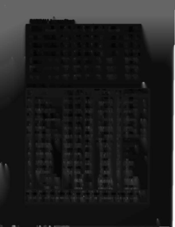
RADICAL! Jumper Chart
GAME
P/N-Ul5
P/N-U27 P/N-U26 P/N-U21 P/N-U22
P/N-U24
JUMPERS
Game uP G.HOM 1 p.OOM2 S.OOM 1 S.ROM2 Sound uP
Transporter
5400-09150-00 A-5343-
A-5M3-
A-5343- A-5343-
5400-09150-00
wi, 2. 4.5.7.8,
2008-2
2008-1 2008-4 2008-3
11.14.16. 17.19
Elvira
5400-09150-00 A-5M3-
A-5343- A-5343- A-5343-
5400-09150-00 wi. 2. 4, 5, 7.8.
2011-2 2011-1 2011-4 2011-3
11. 14. 16. 17. 19
Mous~'
A-5343-
A-5343- A-5343- A-5343-
5400-09150-00 Wl .2.4.5.7.8.
Aroun
5400-09150-00 2009-2 2009-1 2009-4 2009-3
11.14.16.17.19
Game
~-O9150-O0
A-5343-
A-5M3-
Not
Not
Not Used
WI. 2. 4. 5. 7.
Show
2003-2 2003-1
Used
Used
11.14.16.
Pool
A-5343- A-5343-
Not
Not
Not Used
WI . 2. 4. 5. 7.
Sharks
5400-09150-00 2014-2 2014-1
Used
Used
11.14.16.
Radical
1s4oo-09150-OO A-5343-
A-5343-
Not
Not
Not Used
WI. 2. 4. 5. 7.
2015-2 2015-1
Used
Used
11.14.16.
RADICAL!
Solenoid Tobie
Sol.
Wire 1
t;onnectlona
Driver
Solenoid Part Number
Solenoid
FlCJlhlanp Type
Function
Color
CPU Id
Playtleldl
Trnalr
No.
Type
Cabinet
0.
DIsplay Bd; p=PIayfteld
01A 3 Oulhole
Switched Vlo-Bm 1Pll-1
5.11-9:5.14-9 (A)
Q33 AE-23-SOO
OlC 3 Ball Lock Flash«
Switched Blk-Bm (Gry-Bm
5J5-9{C)
Q33 #906 flashlamp
1p
02A3 Ball Shooter Lane Feeder
Switched Vlo-Red
1P11-3
5.11-7:5.14-8 (A)
Q2S AE-23-SOO
02C 3 Left Ramp Flasher
Switched Blk-Red {Gry-Rec
SJ5-8 (C)
Q2S #906 tlashlamp
1p
03A 3 BaR Popper
Switched Vlo-Om 1Pll-4
5.11-6: 5.14-7 (A)
Q32 AE-23-SOO
03C 3 Top Left Flipper Flasher
Switched Elk-Om (Gry-Om
SJ5-7(C)
Q32 #906 tlashlamp
1p
04A3 Top Drop Target Bank
Switched Vio- Yel
1P11-S
5.11.0: SJ4.6 (A)
Q24 AE-2~1200
04C 3 Top Left 8< Left Girt Flash8D Switched Blk-Yel
(Gry-Yel
SJ5-S (C)
Q24 #89 ftashlamp
1p 1b
OSA3 Knocker
Switched Vio-Gm 1P11-6
5.11-4: SJ4-S (A)
Q31 AE-23-SOO
05C 3 Top Spin 8< Jackpot Flashers . Switched Elk-Gm (Gry-Gm
SJ5-4 (C)
Q31 #89 flashiamp
1p 1b
06A3 Bottom Drop Target Bank
Switched Vio-Blu
1P11-7
5.11-3: SJ4-4 (A)
Q23 AE-2~1200
06C 3 Drop Hole 8< Title Flasher
Switched BIk-Biu
(Gry-Blu)
5.15-3(C)
Q23 #S9 flashlamp
1p3b
07A 3 Ball Diverter
Switched Vio-Bik
lP11-S
5.11-2: 5J4-2 (A)
Q30 AE-23-SOO
07C 3 Top Right 8< T-Shirt Flasher
Switched Blk-Vio
(Gry-Vio
5J5-2 (C)
Q30 #89 flashlamp
1p 1b
08A 3 Ball locker
Switched Vio-Gry
lP11-9
5.11-1: 5J4-1 (A)
Q22 AE-23-800
08C 3 Ball Gate 8< Shooter lane Flshr Switched Blk-Gry
(Gry-Blk)
5J5-1 (C)
Q22 #89/#906 flshlmps 1p lb
09
Lwr Dr Bank 8< Lt Face Flasher Controlled Bm-Blk
lP12-1
5.12-9: 5J~9: 2J4-3
Q17
#89/#906~
lp lb
10
Playtield Gnlillum Relay
Controlled Brn-Red lP1'2-2
5J2-S: 5.16-8: 2J4.o
Q9 558Q.09555-01 4a
11
Insert Ilium Relay
Controlled Bm-Orn
lP12-4
5J2-6: 5J~ 7: 2J4-6 Q16 5580-09555-01 4a
12
AjC Select Relay
Controlled Bm-Yel
lP12-5
5J2-5
QS 558Q.09555-01 S
13
Right Ball Gate
Controlled Bm-Gm lP12-6
5.12-4:5J~5
Q15 AE-20-1500
14
Lett Oullane Kicker
Controlled Brn-Blu
lP12-7
5J2-4: 5J~3
Q7 AE-24-900
15
Top Kicker (Sling)
Controlled Bm-Vio
lPI2·S
5.12-2:SJ~2
Q14 AE-23-800
16
lett Curl Ral'l1'
Controlled Brn-Gry
lP12-9
5.12-1:5J~ 1
Q6 #906
fIaIhIaI'r4J
lp
17
Lett Jet Bumper
Special #1 Blu-Bm lP19-7
5.13-7:5J7-7
Q75 AE-23-800
18
lett Kicker (Sling)
Special #2 61u-Red lP19-4
5.13-6:5J7-6
Q71 AE-2~1500
19
Right Jet Bul'l1'er
SpeCial #3 Blu-Om lP19-3
5J3-3:
5.17-3
Q73 AE-23-BOO
20
Right Kicker (Sling)
Special #4 Blu-Yel
lP19-6
5.13-4:
5J7-5
Q69 AE-2~1500
21
Bottom Jet Bumper
Special ;1'5 Blu-Gm lP19-8
5.13-2:5.17-2
Q77 AE-23-800
22
Top Jet Bumper
Special #6 Slu·61k
lP19·9
5.13-1: SJ7-1
Q79 AE-23-SOO
-
LOIl1~rBiQot EIiI2I<~
-
Orn-Vic lP19-1
2J5-5:
2P10-7
Upper Right Flipper
(Siu-V;O)2
(2J10-l: 2P8-15)
FL1I 630/50VDC
(S:k-Siu)
(2J
10-4: 2P8·12j
FL 1l630/50VDC
-
Lower Lett Flil2l2er
Om-Gry lP19-2
2J5-4: 2P10-8
-
Upper Left Flipper
(Blu-Gry?
(2J 10-2: 2P8·14)
FL11630/50VDC
(Blk-Yel)
[2J 10-3: 2P8-13)
Fl11630/50VDC
!i2lu 1. Wire colors, except flipper Om-Vio and Orn·Gry. are ground connections (to coil terminal With unbanded end of cicce). Flipper Orn-Vio and
Orn·Gry wires connect from CPU Board to flipper switch. 2. Flipper connections shewn in braces are from flipper switch to flipper cciI. 3. "A"
circuits are pulsed, when Sol. 12 is de-energized; 'C" circuits are pulsed, with Sol. 12 energiZed. Wire colors in brackets are those from respective A
and C terminals corresponding to the JHermlnal connection listed
tor
the Au. Power Driver ad . which controls the device pulsing by Sol. 12.
4. Relay is mounted on Relay Bd, (4a) pin C-11998-1; (4b) C·11902·1. S. Relay is mounted on Aux Power Driver Bd,
0-12247
in the backbox.