Basic HTML Version


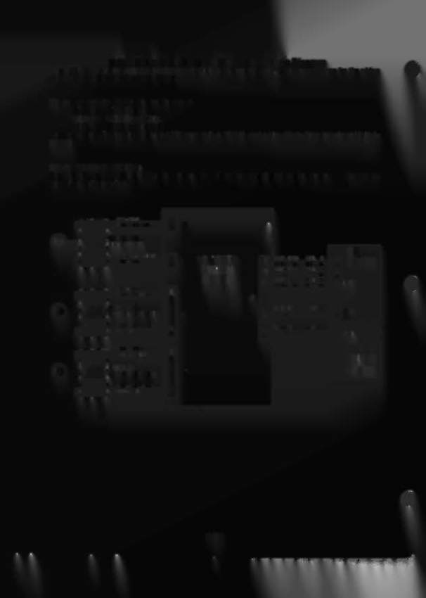
Switch Individual Playfield Opto Switch Wiring Diagram
This diagram shows the wiring for individual playfield opto switches only. See the next page for the wiring
diagram for the ball trough opto switches.
The individual
pJayfield opto switches are:
Switch 36 Right Popper
Switch 42 Left Flipper Opto
Switch 43 Right Flipper Opto
Each of these switches uses a green LED board (pin A-16908), and a blue Photo Transistor board
(pin
A-
16909).
OPTO SWITCH OPERTION:
The ball rolls between the LED board and the Photo Transistor board and breaks the beam. The broken
beam 'makes' the switch.
8-
r-------_,
GRY-BlU
2
I
BlK GROUND
19
J1
: I ••. JI
1
II
SWITCH #36
!
I
i
RIGHT POPPER
CPU
~\J
GRY-YEl.
+12V
9
10"":'OPTO
-
WHT-BRN
COL. 1
r-
BOARD
1
ORG BlU
J2
12
1
2
SWITCH
11
WHT-RED COL.
2 2
'-- ______
-.1
WHT ORG COL. 3
10
3
BOARD
9 WHT-_,,!,El
COL
4
4
B
WHT-GRN COL.
5 5
J20B
-
7
WHT-8lU COL. 6
7
r--------,
GRN-ORG
1
L
_..
BlK GROUND
2
J3
: I ••.. JI
'--
1
1
II
: SWITCH #43
GRN-ORG ROW 3
lI]J206
1
4
I
I
RIGHT FLIPPER OPTO
J4
3
r.RN·-WHT ROW
4
I
1
~\I:
GRY-YEl.
+12V 3
GRY-YEl
+12V
rn
J141
I
WHT ORG
2
RIK
r.Rnt
1oJ[)
5
1
'- ______
-.1
-
-
GRN-RED
-
POWER
r--------,
1
L
BlK GROUND
2
DRIVER
: I •.. I'
I
II
SWITCH
#42
BOARD
I
I
lEFT FLIPPER OPTO
J5
I
~\I ,
GRY-YEl.
+12V 4
WHT RED
~
'- - -______
-.1
8-
8-
3-20