Basic HTML Version


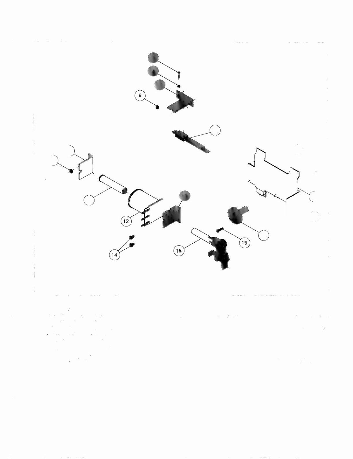

Fliptronic II Flipper Assembly
A-15205-R
A-15205-R-2
A-15205-L-2
(Shown)
A-16976-L
16
• Flipper
'oil's:
I. 1',1,II
Fllpp'T Assemhly i, mounted beneath the playficld, in conjuction with
the
Plastic Flipper
&
Sliaft, an.I Flipper RLlI,kr lIl: tllc'
L1ppl'rsilk olthc playficld.
2. Wul: thr
Hipper.
in UK non-activated position. the E.O.S. Switch contacts must have a gap of .062 (±.Ol) inch. When llippl'l
IS
;rl'tlv;rted switch must close,
J. Any adjustment of the E.O.S. Switch must be made at a minimwn distance of 0.2) inch from the switch body .
.t. I ).Hlgcr blade of E.O.S. Switch must be straight. Gap adjustment is done by adjusting shorter blade.
5. All moving clements of the assembly must operate freely without any evidence of binding.
ft.
Apply Loctit« rv 24) when rc.uaching screws to the Flipper Stop Assembly, the Solenoid Bracket, and the Flipper
BlI,IlIII~.
Judge Dredd
2-17