Basic HTML Version


Left Flipper Circuit
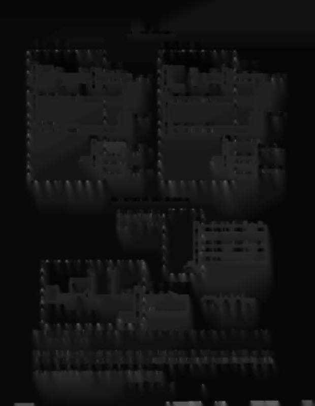
:- FUPTRO-NIC -II BOAR-D -
Flipper Coil Circuits
Right Flipper Circuit
r - - - - - - - - - - - - -
FLiPTRONIC II BOARD
Upper Left
Flipper
Playfield
, Playfie/d
Power
Holdin
Upper Right
Flipper
Power
Holdin
J906
J906
Upper Left
End-ot-Stroke
Switch
,Black-Green
Lower Right
End-ot-Stroke
,Orange
Switch
6>-'__'_:::_:_=: ::" ';!'=-..J
,Black-Violet
4
Upper Right
End-ot-Stroke
Switch
Lower Left
End-ot-Stroke
Switch
H--+="'-"''''''-_j
'Orange
1
_
Flipper End·of·Stroke Switches
- -
-
-
- -
-
-
-
-
F1 Lower Right Flipper
'FLIPTRONIC II
F5 Upper Right Flipper :
BOARD
,
J906 ,
1 ' Black-Green (U4A-5)
0
3 ,Black-Blue
(U4C-9)
0
5
,Black-Gray
(U6C-9)
,
F3 Lower Left Flipper
F7 Upper Left Flipper
41_L~B~la~ck~-~V~io~le~t~~(U~6~A~-~5)~o
r - - - - - - - - - - - - -
, FLiPTRONIC II BOARD
+5V
, Orange
+12V
J906 '
End-of-Stroke Switch
,
1K
, 74HCT244
Dedicated Input
: Orange
,------1
6
f- - '--- -- -''------'
The flipper switch circuits operate similar to the dedicated switch circuit. The circuits are active low and tied to
ground through the switch.
When a switch closes the row side (dedicated input) of the circuit activates. The "+' input to the LM339 drops below
+5V therefore its output is low. Since the row (dedicated input) circuit is tied directly to ground through the switch,
the switch
IS
considered closed by the microprocessor. When the switch opens, the "+' input to the LM339 is above
+5V, its output is high and the row (dedicated input) is inactive.
Judge Dredd 3·22