Basic HTML Version


LAMP MATRIX
Yellow(B+) ~Red
~
1
2
3
4
5
6
7
8
Yellow-
Yellow-
Yellow-
Yellow-
Yellow-
Yellow-
Yellow-
Yellow-
Brown
Red
Orange
Black
Green
Blue
Violet
Gray
J137-1
J137-2
J137-3
J137-4
J137-5
J137-6
J137-7
J137-9
w
098
097
096
095
094
093
092
091
1
Red-
MODE
POWER
LEFT
LEFT
CYBER
CYBER
CYBER
RIGHT
Brown
READY
DOWN
RAMP
LOOP TOP MATRIX
MATRIX
MATRIX LOOP TOP
J133-1090
BLOCK 4
ARROW
13
12
11
ARROW
11
21
31
41
51
61
71
81
2
Red-
DOWNLOAD
N.A.S.
EXTRA
LEFT
CYBER
CYBER
CYBER
CYBER
Black
CURE
BALL
STANDUP
MATRIX
MATRIX
MATRIX
LOCK
J133-2089
ARROW
23
22
21
3
12
22
32
42
52
62
72
82
3
Red-
ACCESS
RIGHT
SECTOR
RIGHT
CYBER
CYBER
CYBER
SECTOR
Orange
CODE 2
RAMP
2
RAMP
MATRIX
MATRIX
MATRIX
7
J133-4088
BLOCK 4
BLOCK 1
33
32
31
13
23
33
43
53
63
73
83
4
Red-
ACCESS
SECTOR
LEFT
LIGHT
RIGHT
RIGHT
POPPER
LEFT
Yellow
CODE 1
6
RAMP
SPINNER OUTLANE
RETURN
TOP
OUTLANE
J133-5Q87
BLOCK 2
LANE
ARROW
14
24
34
44
54
64
74
64
5
Red-
UPLOAD
RIGHT
LEFT
BIG
BONUS
SECTOR SECTOR
LEFT
Green
RAMP
RAMP
POINTS
HELD
5
3
RETURN
J133-6 Q86
BLOCK 2
BLOCK 1
LANE
15
25
35
45
55
65
75
85
6
Red-
LEFT
HOLD
SECTOR GIGABYTES BONUS
SPINNER
CRAZY
BALL
Blue
JET
BONUS
1
4X
MILLIONS
BOB'S
LAUNCH
J133-7085
LANE
16
26
36
46
56
66
76
86
7
Red-
MIDDLE
RIGHT
NOT
LIGHT
BONUS
CYBER
MODE
BUY-IN
Violet
JET
STANDUP
USED
EXTRA
3X
LOCK
START
BUTTON
J133-8084
LANE RIGHT BLOCK
BALL
2
17
27
37
47
57
67
77
87
8
Red-
RIGHT
RIGHT
SHOOT
QUICK
BONUS
INNER
CYBER
START
Gray
JET
STANDUP
AGAIN MULTIBALL
2X
LOOP
LOCK
BUTTON
J133-9 Q83
LANE
LEFT BLOCK
TOP
1
18
28
38
48
58
68
78
88
J1XX
=
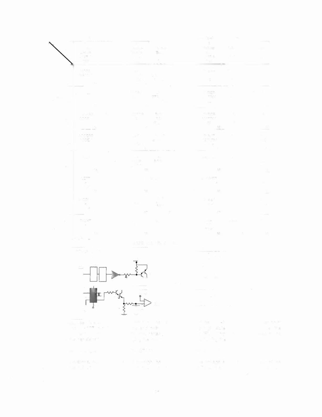
POWER DRIVER BOARD
LAMP MATRIX CIRCUIT
r---------- --------------------------
-
,
: POWER DRIVER BOARD
:
,
,
i
Column (example)
+lBV
i
,
,
,
,
,
,
,
,
,
,
I
J1371
,
,
:
x
H-,...:.Ye""lIo::.::w_:-
x=xx::........l-.!Y---I~-,
,
,
,
,
I
J1J4
1
i
~ R e=d~-X=XX~------~
, , , ,
,
,
, , , , ,
:
L
~
The microprocessor sends a signal to the column circuit causing the output of the UNL-2B03 to toggle. When point
"A" drops low, the TIP107 transistor conducts and point "8" changes to a high state. At the same time, the
microprocessor drives the input of the 74LS74 low, causing a high at output "F". A high state at the base of the
TIP102 causes the transistor to conducts, bringing the row circuit to ground and turning the lamp on.
COLUMN A B
H L OFF
L H ON
PLAYFIELD
ROW
NORMAL H
OPERATION H
The microprocessor changes the input of the 74LS74 to a high state to turn the lamp off.
In overcurrent conditions, the lamp is shut off through the comparator. If the voltage at the negative input of the
LM339 rises above 1.4V, the output changes to a low, which is fed back to the 74LS74 and shuts the row circuit off.
3-4