Basic HTML Version


3.e
Adjust the red and green drive controls
for
"neutral
white"
on
high whlte picture areas . Generally these
controls will be lett
at
mech. centre.
3.7
Note:
When monitor is re-connected with the game
the screen control
(G2) may require a Slight
adjustment to obtain proper black level. (the black
portion of picture just extinguished).
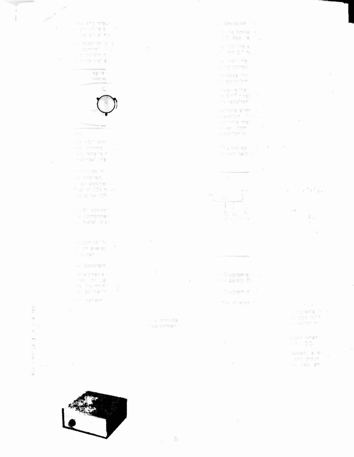
[REAR VIEWI
Figure 11
4.0
Power Supply
The regulated +81 control
(A909) has been factory
adjusted and normally requires no adjustment.
However. if any repairs have been made to the chassis
it
is recommended that this adjustment should be
made .
a) Allow 5 minutes to warm up.
b) No signal applied.
c) Connect an accurate D.C. voltmeter to TP-91 or
the emitter of X04 power regulator transistor .
d) Adjusl AgOg
for
120V. ,See fig.
I}
Note:
Should +81 control be set too high. it may cause
possible component damage. Use an accurate
D.C. voltmeter to set 81 (8+).
5.0
Focus
Adjust focus control
for best overall definition and
picture detail an average signal applied . (Highlights
should be favoured .)
6.0
Color Service Generator tor G07 Monitor
Electrohome has developed a color service generator that is
specifically designed lor use with the G07 color data
monitor. It provides the monitor with both horizontal
and
vertical sync, as well as the following test patterns:
1) Fine cross-hatch pattern
2) Broad bar cross-hatch pattern
3) Complete field
Three color selection switches, red. green and blue. provide
the ability to display the above patterns in the three primary
colors as well as the three secondary colors.
This product may be ordered from:
Contracts Marketing
ELECTAOHOME Electronics
809 Wellington
51.
North
Kitchener, Ontario
Canada N2G 4J6
Telephone : (519) 744-71
I
1. Ext . 567
7.0
7.1
X.Ray Emlilion Check
7.2
Assure the power supply 81 IS properly adjusted to
120V DC See Item 4.0 (page 8)
Assure that the anode voltage does not exceed
max.
85
per Item 2.0 page 4.
Assure that the high voltage hold down Circuit is
operating correctly . Use the follOWing procedure .
a) Increase the 81 greater than 138.5V by shorting
collector/emitter
of the power regulator, X04.
b) Observe that the anode voltage (EHT) goes to
0
If
the EHT does not go to O. a fault must be located
and repaired.
c) Aemove short and set should return
to
normal
operation . (Note . after the short is removed some
monitors may not restart. In this case , remove
power from monitor momentanly and normal
operation Will be restored.
Note:
The protector ci reu it consi
sts
of the com ponents
shown below in Fig.
13
wi tn a
c
ircu It descri plion .
7.3
~7'-
">-?~""";;J
j
...,....
.._..
.
rc
S("l 1-I} .1 l2 U
~'lir--\~lO
I; ...
;oa
L:.
•.••
0.
f" ...
or
r ~
i
.
I
.
II
•
i ~
10~
'\ lUi
~ ~~ iii
L""1'"
~
10 ~
2Sc'!.4C
I .,- i~ ~~O!)! :\·2
.;.------,
~JO,J
l~.
J.68
~M1.
0..:.
1
"4&a
.,;,
l
Cro\ not
lOOtl-b ":",1
lC.o41'11
FIgure 13
8.0
Circuit Diagram and Description of High Voltage Hold
Down or Safety Circuit
8.1 Circuit Diagram of High Voltage Hold Down Circurt.
8.2 Operation of High Voltage Hold Down Clrcuit .
The high voltage hold-down circuit protects the high
voltage circuit from dangerous voltage with snort
circuiting between emitter and collector of power
regulating transistor.
The base voltage of X701 is increased when the
B 1
voltage is increased more than 138.5 V DC.
When the base of X701 is increased. a short is
produced by X701 between pin 11 and ground of Ie
501, shutti n9 dow n the horizon tal osc. and h ig h
voltage.
.
33