Basic HTML Version


483
position and the ADVANCE pushbutton pressed once or
twice as described above. Note that for test 4 function
numbers 6 and 8 thru 14, values above 09 will not be dis-
played correctly. Refer to Table 1 for an explanation of
the values read out during this test.
AUTO CYCLE MODE
As an aid in diagnosing intermittent problems or as a
means to let the machine cycle itself through portions of
the diagnostics, provision was made for the AUTO
CYCLE MODE. This mode will sequence through the
digit display test, go to test Oland flash the lamps 128
times then go to test 02 and energize each solenoid then
digit test, test 01, etc. This can be allowed to run
indefinitely or until the ADVANCE pushbutton is
pressed to regain control of the diagnostics.
To enter the AUTO CYCLE MODE:
1. Turn game OFF then turn game ON.
2. Press the diagnostic pushbutton on the CPU Board to
enter diagnostics.
3. Set the data and function switches as follows:
DAT A SWITCH (TOP SWITCH) - Turn all switches
OFF. FUNCTION SWITCH (BOTTOM SWITCH) -
Turn all sitches OFF then turn ON only switch 1.
4. Press ENTER pushbutton on CPU Board. The two
LEDs will blink to accept the data.
5. Place the AUTO/MANUAL switch to AUTO.
6. Press ADVANCE pushbutton ONCE. The AUTO
CYCLE MODE will begin and continue until the
ADV ANCE pushbutton is pushed again to regain
manual control of the diagnostics or the machine is
turned OFF.
REPLACEMENT OF PROMs OR CPU BOARD IN
PROTOTYPE GAMES
When replacing PROMs CPU Boards in DISCO FEVER ,.
games it is necessary to determine if the game has pro-
totype or production wiring. Games using Revision A
PROMs require prototype wiring and those using Revi-
sion C PROMs require production wiring.
Games with prototype wiring use solenoid 13 for
the
sound alternator with a Brown-Green lead connected to
2P9 Pin 3. Games with production wiring use solenoid 5
for the sound alternator and the Brown-Green lead is con-'
nected to 2Pll Pin 9.
Prior to replacing the PROMs or CPU Board inspect the
2P9 and 2Pll connectors. If the game has production wir-
ing, no change must be made. However, if the game has
prototype wiring, proceed as follows:
1. Make sure the power is off.
2. Unplug connector 2P9 from the Driver Board.
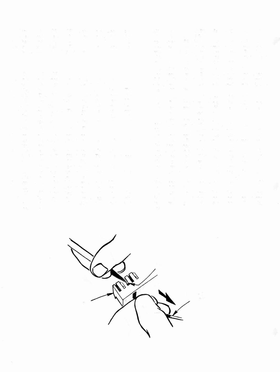
3. Using a miniature screwdriver or other tool with a
small point, depress the tab (see sketch) on pin 3 while
pulling on the Brown-Green wire and remove the pin
from the connector.
4. Inspect the tab and if it has been bent in, pull it back
out so that the pin will latch again when it is reinserted.
5. Carefully cut the tie wrap on the 2P9 harness and pull
the Brown-Green lead from the harness.
6. Unplug connector 2Pll and insert the pin into position
9.
.t
7. Reconnect the two connectors and replace the PROMs ,
or CPU Board.
8. Start a game. Proper operation of the sound alternator
is indicated by a start-up tune. If the sound alternator
is not working properly, a single note will be played
instead.
2P9
20
BRN-GRN
WIRE