Basic HTML Version


LAMP MATRIX
Yellow (8+)
_@_
Red
~
1
2
3
4
5
6
7
8
Yellow-
Yellow-
Yellow-
Yellow-
Yellow-
Yellow-
Yellow-
Yellow-
Brown
Red
Orange
Black
Green
Blue
Violet
Gray
J121-1
J121-2
J121-3
J121-4
J121-5
J121-6
J121-7
J121-9
w
096
0100
095
099
094
098
093
097
1
Red-
CIROUS
CIROUS
SIDE
RING-
CRANK
MIDDLE
WOW
EXTRA
Brown
"R"
"I'
SHOW MASTER
TOP
JACKPOT
RIGHT''W'
BALL
J125-10104
LEFT
TARGET
11
21
31
41
51
61
71
81
2
Red-
GRID
CIROUS LEFT LOOP
RING-
CRANK
RIGHT
WOW
TOP
Black
TOP
"C'
TOP
MASTER
2
JACKPOT
"0'
JET
J125-2010B
2
TARGET
BUMPER
12
22
32
42
52
.62
72
82
3
Red-
CIROUS
GRID
LEFT LOOP
RING-
CRANK
LIGHT
WOW
MIDDLE
Orange
"0"
MIDDLE!
3
MASTER
3
STANDUP
LEFT"W"
JET
J125-4 0103
LEFT
3
TARGET
TARGET.
BUMPER
13
23
33
43
53
63
73
83
4
Red-
CIROUS
GRID
LEFT LOOP
RING-
CRANK
LOCK
RING
LOWER
Yellow
"U'
BOTTOM!
2
MASTER
BOTTOM STANDUP
liN"
JET
J125-50107
LEFT
4
TARGET
BUMPER
14
24
34
44
54
64
74
84
5
Red-
GRID
GRID
LEFT LOOP
RING-
RIGHT
RING
RING
RIGHT
Green
TOP/RIGHT
BOTTOM
1
MASTER
LOOP
IIR~
"G'
IN-LANE
J125-60102
RIGHT
TOP
15
25
35
45
55
65
75
85
6
Red-
CIROUS
. GRID
MULTIBALL
SPECIAL
RIGHT
RING
RIGHT
VOLT
Blue
·S"
MIDDLE
LOOP
"I'
OUTLANE
LEFT
J125-70106
3
16
26
36
46
56
66
76
86
7
Red-
GRID
GRID
LOCK
RAZZ
RIGHT
SHOOT
LEFT
VOLT
Violet
MIDDLE!
BOTTOM!
LOOP
AGAIN
IN-LANE
RIGHT
J125-80101
RIGHT
RIGHT
2
17
27
37
47
57
67
77
87
8
Red-
lEFT
GRID
SPOT
FRENZY
RIGHT
LEFT
SKILL
START
Gray
JACKPOT
TOPILEFT
MARVEL
LOOP
OUTLANE
RING
BUTTON
J125-90105
1
18
28
38
48
58
68
7S
SS
J1XX
=
Power Dnver·Board
LAMP MATRIX CIRCUIT
c-~--------------------------------
-----+-il'1---------------------,
COlUM
NAB
Column (example)
-'='-'''-=.!.!!!.!--¥.'7-tT-f=;:;::-
H L OFF
L H ON
PLAYFIElD
J1XX
Red-XXX
_____________________________________
'-
.1
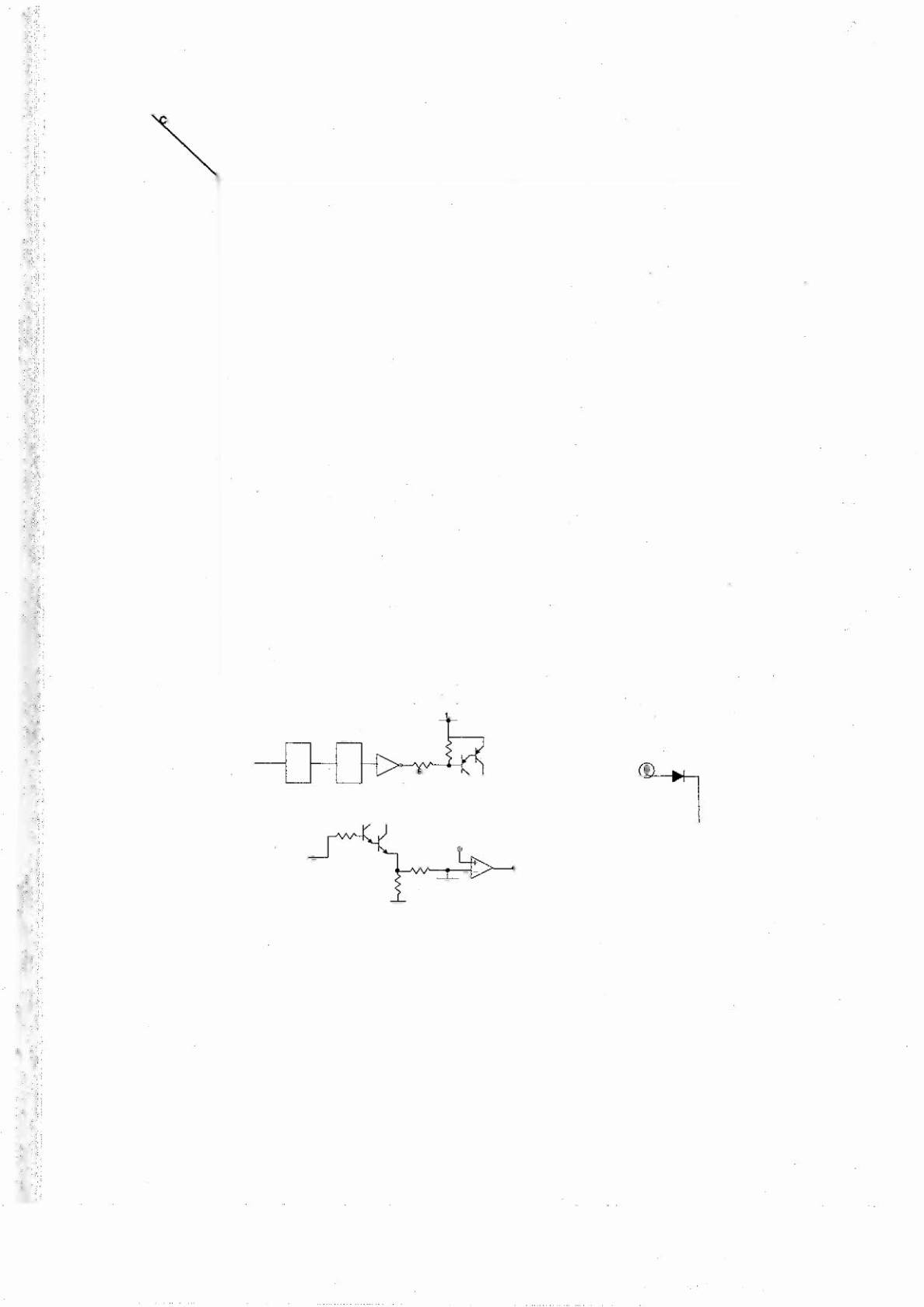
The microprocessorsends a signal to the column circuit causing the output of the UNL-2803 to toqqle,
When point "A" drops low, the T[P107 transistor conducts and point "B" changes to a high state, At the
same time, the microprocessor drives the input of the 74LS74 [ow, causing a high at output "F". A high
state at the base of the TIP102 causes the transistor to conducts, bringing the row circuit to ground and
turning the [amp on. The microprocessor changes the input of the 74LS74 to a high state to turn the [amp
off. In overcurrent conditions, the lamp is shut off through the comparator.
If the voltage at the negative
input of the LM339 rises above 1.4V, the output changes to a low, which is fed back to the 74LS74 and
shuts the circuit off.
3-4