Basic HTML Version


"I"
..
;"
"
,~
.
,
a
rI
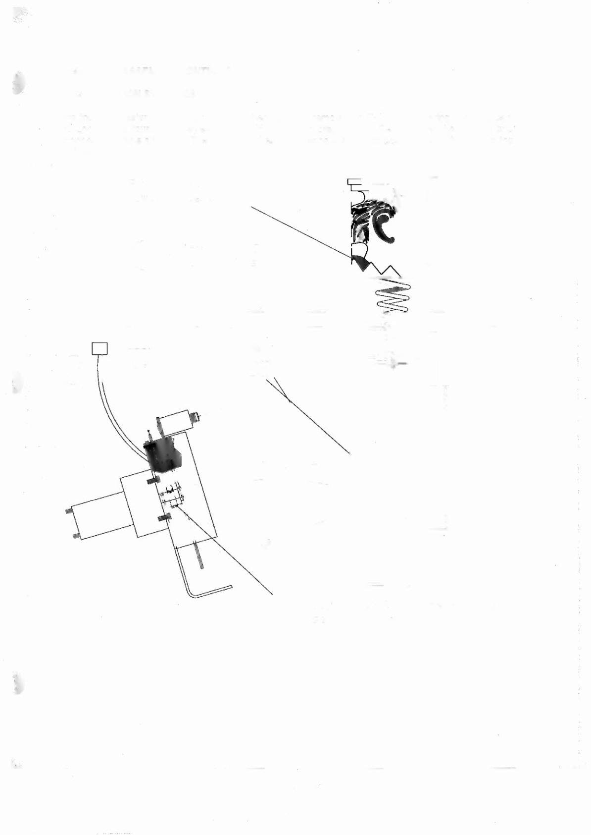
RINGMASTER ASSEMBL Y CONTINUED ...
ADJUST POSITION SWITCHES
Move the Ringmaster to the down position, then carefully remove the E-ring" and bearing from the cam
hub. Loosen the tour (4) #8 screws that hold the motor bracket on. Gently lower the bracket and
disconnect the cable attached. The micro switches can now be adjusted to close while on the apex of the
switch wire.
CD
Put Ringr'lO.ster in
lowe s t posit on.
~ ReMove (4) #8
~ screws
s,
wo.shers
Li ft Ou t
~
@
o .djust switches o.s needed
see next po .ge .
h65