Basic HTML Version


6. Unlock the marquee and raise it until the hinged marquee support arm (interior right side) is
accessible; lock the marquee arm in its straight position. Reach in the backbox and unlatch the
upper playfield. Tilt the upper playfield forward and carefully lay it on the lower playfield glass. On
each of the two inserted carriage bolts protruding through the inside cabinet wall, place a
flatwasher, a lockwasher, and a wingnut. Secure the upright backbox by tightening the wingnut.
7.
While accessible, ensure that the pivot bracket of the Freestyle kickbig on the upper playfield is
adequately lubricated to provide proper operation.
NOTE: Satisfactory operation of the
Kickbigs, Kickers, and Eject Holes devices on both the upper and lower playfields is EXTREME-
LY IMPORTANT for proper game play. An essential means of keeping these devices operating is
LUBRICATION.
8.
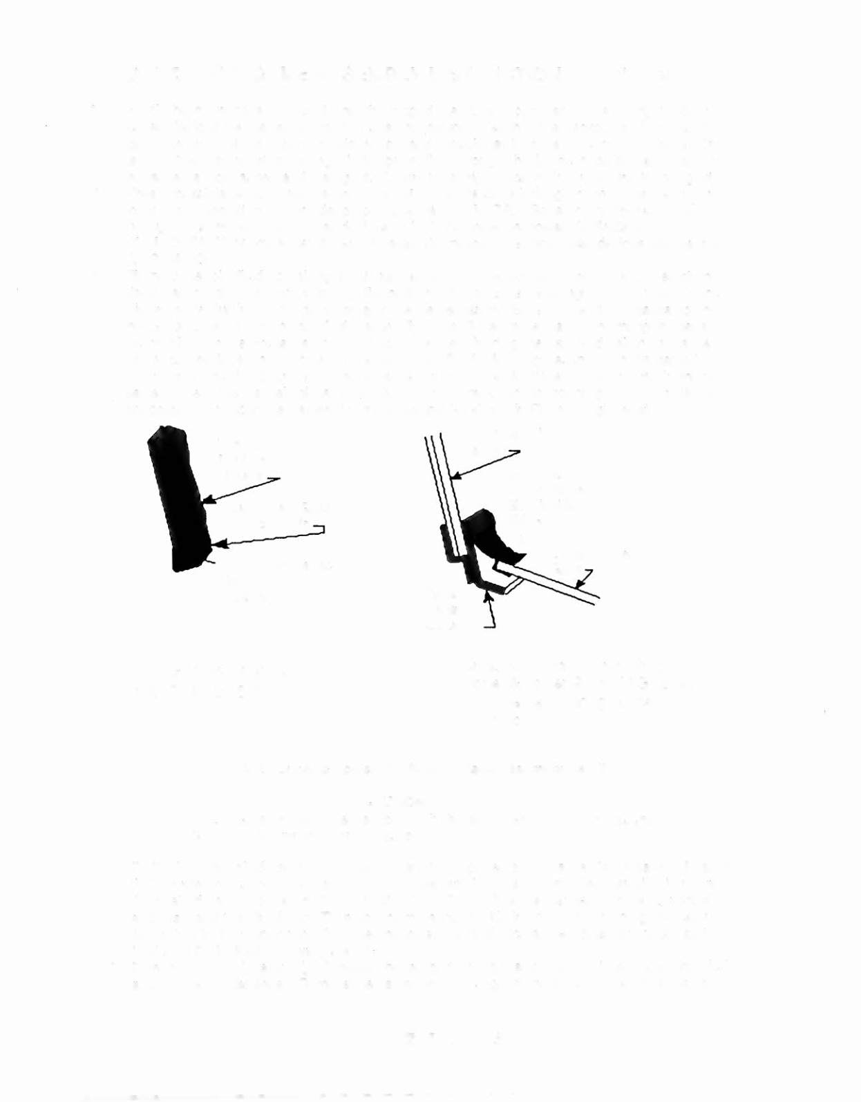
Tilt the upper playfield up, raiSing it until its playfield glasses can be moved safely. Detach the
black plastic glass protector strip from the bottom of the glasses (see Figure
2,
left view); place
this protector strip inside the game for later use, as necessary. Slide the playfield glasses up until
the captured ball area of the playfield is accessible. Install the smaller ball (from among the parts in
the cashbox) in the Freestyle area. Remove the foam holding the captured ball in its playfield
(upper center) location. Locate the stainless steel Barrier Molding Assembly (in the game legs
box); the Barrier Molding Assembly replaces the black plastic glass protector strip (removed
earlier). Clean the playfield glasses and slide them downward in the mounting grooves, until they
are properly located in the Barrier Molding Assembly (as shown in Figure 2, right view).
Up Per PIa.y1iel d
GI83ses
(R em ove an d re plec e
with BamerMolding
ksembly.)
Berrier
Molding
ksembly
Black PI83tic
Lover PIa.y1ield
GI83s Molding
St7
lEAN7Y:JJ IllJlJN
GAME ASSEMBLY INSTRUCTIONS
(Continued)
Upper Playfield Glass
with Protector Strip
Cross-sectional View of Proper
Upper
&.
tower Playfield Glasses
Arrangement during Game
Assembly
Figure 2. Upper & Lower Playfield Glasses Assembly Details
«,;&:.QJJil1l©1Nl
NEVER
raise or lower the backbox with the steel Barrier Molding Assembly
attached to the upper playfield glasses.
9.
On the lower playfield, remove the foam holding the captured ball in its playfield location. Ensure
that the pivot brackets on the Kickbig, Eject Holes, and Kickers are properly lubricated to provide
the desired device operation. (Refer to step 7 NOTE.) While the playfield can be moved, lift it
and assemble the Plumb Bob Tilt mechanism on the leftside interior panel of the game cabinet.
Adjust this tilt for proper operation
after
the lower playfield pitch angle adjustment is completed.
(Refer to
©&:'l)J]lIU@1Nl
following step 1"1.)
10. Extend each leg leveler
slightly
below the leg bottom, so that all four foot pads are extended
about the same distance. Remove the cabinet from its support and place the game on the floor.