Basic HTML Version


TEST/DIAGNOSTIC PROCEDURES
(Continued)
JJBAf.!ZAlI
IJU/JN
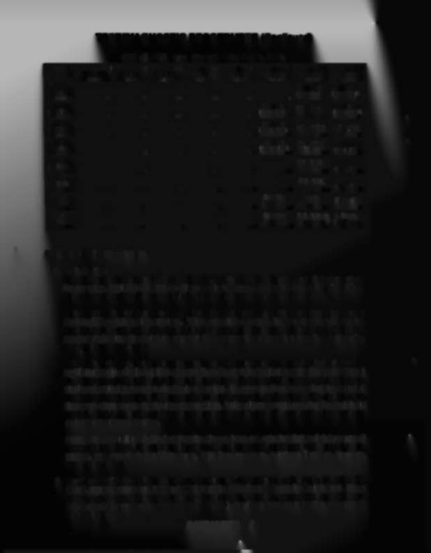
Upper Playfleld
Switch-Matrix Table
~
,
045
2
Q49
3 044
4
048
5
043
6
047
7
042
8
046
GRN·BRN GRN·RED GRN·ORN
GRN·YEL
GRN·BLK
GRN·BLU
GRN·VIO GRN·GRY
W
1J8·1
1J8·2
1J8·3
1J8·4
1J8·S
1J8·7
1J8·8
1J8·9
WHT·
Freestyle
Freestyle
1
BRN
(lower Blue)
(lower Green)
lJ10·9
1
9
17
25
33
41
49
57
WHT·
Freestyle
Flipper Post
Freestyle
2
RED
(upper Blue)
(upper Graen)
1J10·8
2
10
18
26
34
42
50
58
WHT·
Freestyle
Lower lifter
Mouse Hole
3
ORN
(lower Yellow)
1J10·7
3
11
19
27
35
43
51
Drain
59
WHT·
Freestyle
Defeat Red
A
4
YEL
(upper Yellow)
Cliff Jump
Stndup
Tgt60
lJ10·6
4
12
20
28
36
44
52
WHT·
Defeat Yellow
B
5
GRN
Roll-Under
Stndup
Tgt61
1J10·S
5
13
21
29
37
45
53
WHT·
DeleatBlue
C
6 BLU
1Jl0·3
6
14
22
30
38
46
Ron-Under
5 4
Stndup
Tgt62
WHT·
Freestyle
Target
Upper Ufter
7
VIO
(lower Red)
Captive Ball
1J10·2
7
15
23
31
39
47
55
63
WHT·
Freestyle
Deleat Green left lock
8
GRY
(upper Red)
Siandup
Tgt
Ball Popper
1J10-'
8
16
24
32
40
48
56
64
SWITCH TESTS (Contlnued).
2. Switch Edges.
From the Switch Levels Test, press ADVANCE. Observe that the Player 1 and 2 displays show
the message, SWITCH EDGES; the Player 3 display shows 07 (Switch Edges Test identifier).
The right portion of the Player 3 display is blank, indicating that no switch is actuated.
This test permits the operator to test whether actuating a switch provides the proper signal to the
System-t
t
B switch testing program. When actuating a switch, the operator should see the
switch's name and number (in the Player 1, 2, and 3 displays, respectively). If no indication
appears at the time the switch is actuated, the operator then knows that there is a malfunction
associated with that switch.
Using this technique, the operator can test each switch appearing in the
BANZAI RUN
switch
problem reporting displays (either at game Tum-On or at the beginning of the Diagnostic Tests)
to determine whether the switch can be actuated. If the switch's name and number are
displayed while the operator checks its operation, the operator then knows that the reported
problem with that switch is NOT currently caused by a switch malfunction. The operator can
then seek other causes for the reported problem, being almost certain now that the switch did
not fail.
This test is also useful when the operator is adjusting the sensitivity of
a
particular
switch's actuation mechanism.
Among the possibilities is the fact that the players have not actuated that switch because of
some other problem: the operator should try to analyze what could-cause the switch to be
missed, and remedy that problem cause. With these new tests, switch problems are, therefore.
more easily isolated.
3. Playfield or CPU Board?
To determine whether a switch problem is in the playfield or the CPU
Board, remove connectors 1P8 and 1Pl 0 from the CPU Board. Begin the Switch Test. Use a
jumper wire to simulate switch actuation. For example, placing a jumper between 1J10-9 and
lJ8-2 should (based on the Switch-Matrix Table) should produce an indication of switch 09
being actuated.