Basic HTML Version


LAMP MATRIX
YeIlOW(B+)~
Red
~
1
2
3
4
5
6
7
8
Yellow-
Yellow-
Yellow-
Yellow-
Yellow-
Yellow-
Yellow-
Yellow-
Brown
Red
Orange
Black
Green
Blue
Violet
Gray
J121-1
J121-2
J121-3
J121-4
J121-S
J121-6
J121-7
J121-9
ow
096
0100
09S
099
094
098
Q93
097
Red-
RIGHT
1
Brown
SUPER BIG-O-BEAM TRACTOR
LOOP
ATTACK MARTIA"N"
CAPTURE
SHOOT
J12S-10104
JETS
1
BEAM 1
ARROW MARS
TARGET
1
AGAIN
11
21
31
41
51
61
71
81
Red-
CENTER
2
Black
SUPER BIG-O-BEAM TRACTOR
RAMP
D.C.
MARTI"A"N CAPTURE
LEFT
J12S-20108
JACKPOT
2
BEAM 2
ARROW U.S.A.
TARGET
2
OUTLANE
12
22
32
42
52
62
72
82
Red-
MARTIAN
LEFT
ATOMIC
3
Orange
ATTACK BIG-O-BEAM TRACTOR
TOP
LONDON BLASTER CAPTURE
LEFT
J12S-40103 MULTIBALL
3
BEAM 3
LANE
ENGLAND
1
3
RETURN
13
23
33
43
53
63
73
83
Red-
LEFT
RIGHT
RIGHT
ATOMIC
LEFT
4
Yellow
ANNIHILATION
RAMP
RAMP
TOP
LIGHT
BLASTER
LOOP
RIGHT
J12S-S 0107
JACKPOT
JACKPOT
LANE
LOCK
2
JACKPOT
RETURN
14
24
34
44
54
64
74
84
Red-
RETURN
LEFT
RIGHT
LEFT
ATOMIC
LEFT
5
Green
TO
RAMP
RAMP
MOTOR
LOCK
BLASTER
LOOP
RIGHT
J12S-60102
BATTLE
ARROW ARROW BANK
1
3
ARROW OUTLANE
15
25
35
45
55
65
75
85
Red-
CENTER
RIGHT
6
Blue
CON~UER
LOCK
MARTIAN
MOTOR
PISA
LOOP
"M"ARTIAN LAUNCH
J12S-70106
MARS
2
ATTACK
BANK
ITALY
JACKPOT
TARGET
BUTTON
16
26
36
46
56
66
76
86
Red-
RIGHT
7 Violet
S-WAY
LOCK
RULE
MOTOR
BERLIN
EXTRA
M"A"RTIAN
NOT
J12S-80101
COMBO
3
UNIVERSE
BANK
GERMANY
BALL
TARGET
USED
17
27
37
47
57
67
n
87
Red-
CENTER
STROKE
8
Gray
DROP
RAMP
OF
MAR"T"IAN
PARIS
MARrl"AN MA"R"TIAN
START
J12S-9010S
TARGET
JACKPOT
LUCK
TARGET
FRANCE
TARGET
TARGET
BUTTON
18
28
38
48
56
68
78
88
J1XX - Power Dnver Board
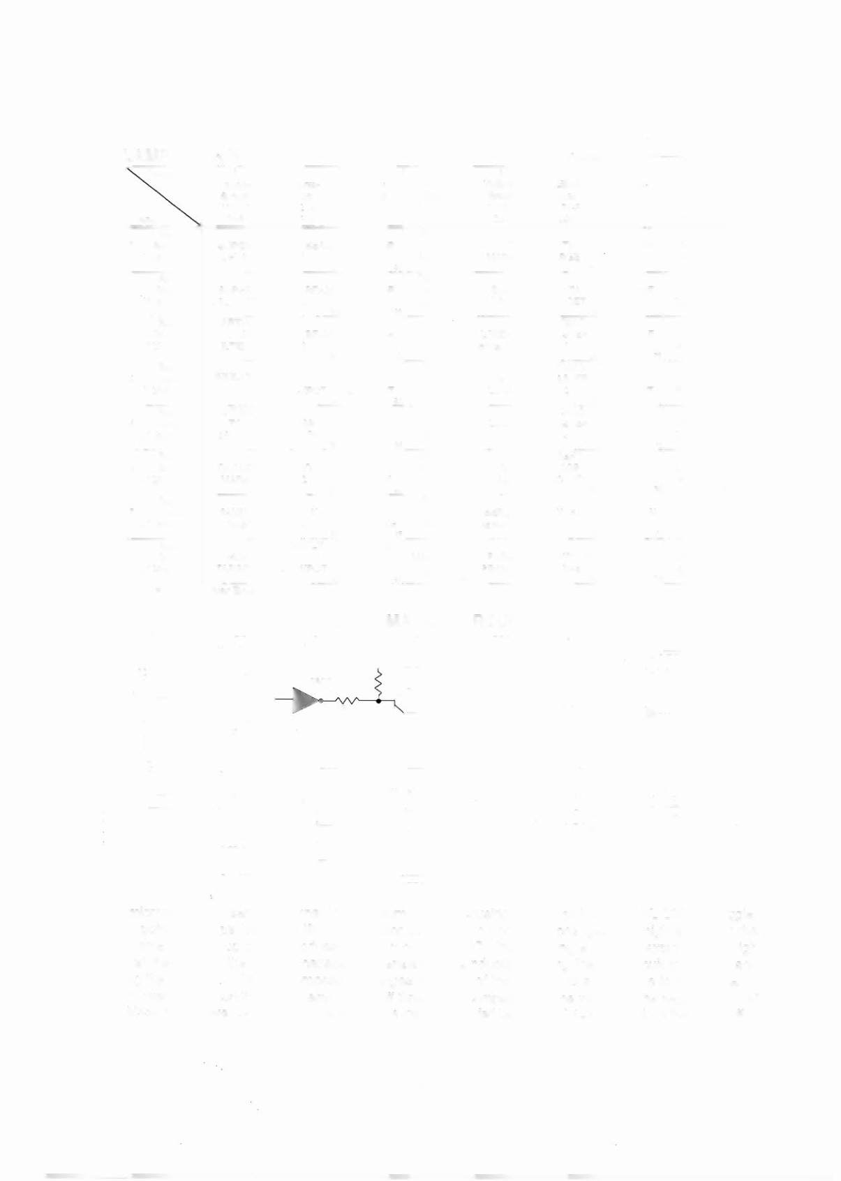
LAMP MATRIX CIRCUIT
r - - -
-_._------ --------------------- -- ------ ------,
.
(
)
+
18V
COlumn example
T
COLUMN A
B
H L
i
OFF
L H iON
TIP I 07
POWER DRNER BOARD
JIXX
'---'--B---
- -0
Yellow-XXX
©
~I
:
PLAVF~E:JLD
Jfl:
.---- ------1LJ :
Red-XXX
X
ROW ,ttD E F Gjg
N RMAL H L H L HOFF
OPERATION H L L H L ON
Row (example)
I
~------------- ------------ ------------ ------------ -----------~
The microprocessor sends a Signal to the column circuit causing the output of the UNL-2803 to toggle.
When point "An drops low, the TIP107 transistor conducts and point "S" changes to a high state. At the
same time, the microprocessor drives the input of the 74LS74 low, causing a high at output "F". A high
state at the base of the TIP102 causes the transistor to conducts, bringing the row circuit to ground and
turning the lamp on. The microprocessor changes the input of the 74LS74 to a high state to turn the lamp
off.
In over-current conditions, the lamp is shut off through the comparator.
If the voltage at the negative input of
the LM339 rises above 1.4V, the output changes to a low, which is fed back to the 74LS74 and shuts the circuit off.
3-4