SEO Version


UNIQUE PARTS FOR SPECIFIC 6Af1ES
F-14
TOMCAT
(554)
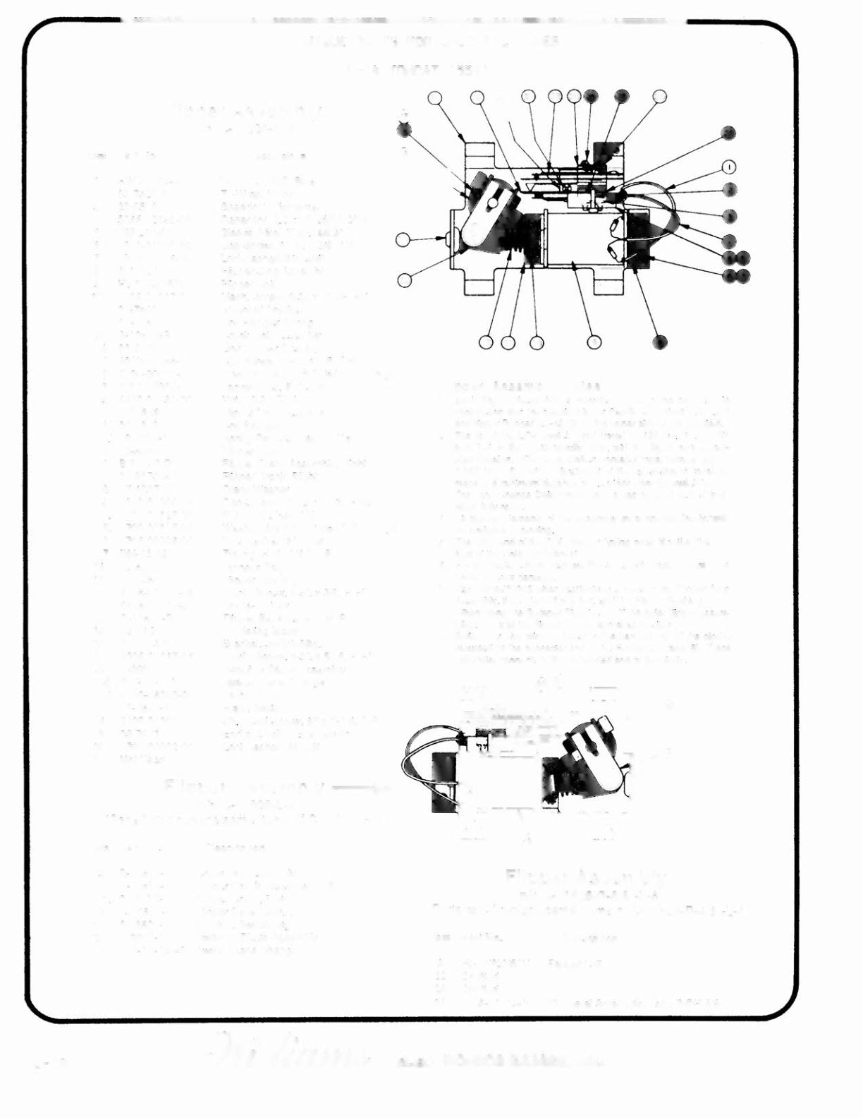
Flipper Assembly
pin C-11626· R·4
lIem Part No,
Descriptio"
Wore, 18 AWG, Blue
Ty·Wrap, Nylon
Speednut, Tinnerman
Capacitor, 2 2 ",Fd, 250V, 20%
Sleeve, Vinyl (Cap. leads)
Cap Screw, 10·32
x
3/8, AH
Lockwasher,
It
10 split
Flipper Stop Assembly
Flipper Coil
Mach. Sorew, 6·32
x
1/4, P·RH·S
Solenoid Bracket
Coil Plunger Spring
Crank
Link
Assembly
Link Spacer Bushing
Cap Screw, 10-32
x
7/8, SH
Washer. 5/8 o.d. x 13/64 i, d. x 16 qa.
Locxwasher.
It
10 split
Nut, 10-32 ESNA
Flipper Unk Assembly
Coil Plunger
Spring Pin,
5132
dia. ~' 7/16
Flipper Link
Flipper Crank Assembly, Right
Flipper Crank, Right
Crank Washer
Cap Screw, 10·32
x
1·1/8,
HCS
Nut, 10·32 Hex Hd_
Washer, 5/8 o.d, x 13/64 i, d. x 12 gao
l.ockwasher
#
10 split
Tubing, H. S, 114DWP
Bumper Plug
Flipper Bushing
MaCh. Screw, 6-32
x
3/8, P·PH
Nut. 6,32 He.
Flipper Base Assembly, R.
Insulating Blade
Bracket, Switch Mtg
Mach. Screw. 6-32
x
5/16, P·RH·S
SwitCh & Diode Assembly
Switch, Lane Change
Diooo,1N4001
Plate. Switch
Sh. Metal Screw. #5
x
1·1/4,
Ene
of
Stroke (EOS) Switch
Lockwashsr 116split
Description
Crank Link Assembly
F'lipper Crank Assembly, lett
Flipper Cran!.., Lett
Flipper Base Assy. L.
Bracket. Switch MIg,
Switch & Diode Assembly
Switch, lane Change
1&
13
Flipper Assembly Not es
1
Each Flipper Assemb:ly
;s
mounted beneath
the
playlield, in
conjunction with the plastic Ftipper Paddle and Shalt (20"92501
and
tlipper Rubber(2H;S 19)
011
the upper side 01the playlield_
2 The
lip 01the EOS Switch must travel 0_0150 (. 010.• _000)
inch. belote the contacts lully open, wilh the Hipper in the
actu-
aled position. The EOS Switch contacts must have a gap 01
0.062 (i ,015)
inCIl,
Adiustmenl of
Ihe
EOS Switch must be
made
at
I I
minimumdistance 010.25 inch Irom the switchbody,
:) The LaneChange Switch musl have a gap 010.046 (i_015) 'inoll.
when tully open_
4
All movi
r.g
€I
I
€I
me
nts
01
t
he a
55
embly must operate I
fe
el
y.
'with
nc evidence
01
binding.
5 The large
end ot
rhe Coil Plunger Spring must tit within
me
lour
tugs
01
the Sotenoid Bracket.
6
For ceil reptacemenl, remove the Solenoid Bracket (item
3)
10
prevent scmw
darnaqe.
7 Use Loclit""" 242 wilen
reauachinq
screws to tile Flipper Stop
Assembly, the Solenoid Bracket, and Ihe Flipper Bushing,
8
When using lhe Bumper PIU9(item 1,3)on older Ilipp<!rassern-
blies. readjust the tlipper paddle and shalt position.
9 Solid color blue wire connects to tile banded end 01 Ihe diode.
mountedon the connector end ol
the
FlipperCoil (item
8), Trac e
color wire connects to the unbanded end 01the diode.
13
Flipper Assembly
,._
pIn C-11626-L-4
(Parts listed replace same Items
or
C·11626·R·4)
5 -18
1
2
3
4
5
6
7
8
9
HW-30018-6
03·7520·2
20·6516
5045-1 2098 -00
RM·21·06
4010·01066·06
4701 ·00004 ·00
A·10821
FL·11630/50V
10 4006·01017·04
11 01·7695
12 10-376
13 B·' 0655-R
a) 02-4179
b) 4010-01086-14
c) 4700-00023-00
d) 4701-00004-00
e) 4410-01132-00
n
A-l0656
1.) 02-4219
2.)
20-9370-1
3) 03,8050
g) B·l 0657·R
1.) 01·8073·R
2,) 17·1037
3,) 4010·01066·18
4.) 4410·01127·00
5_)
4700-00107·00
6_) 4701·00004·00
7.) RM-23·06
14 23-6577
15
03-7568
16
4006-01005-06
17 4406-01117-00
18 C-11627"R
19 06-14G
20 01-8623·R
21 4006·01017·05
22 B·9951
a)
SW·1A·150
b) 5070·06258-00
23 0 '-3670-1
24
25
26
27
4105-01001·20
03·7811
4701·00002·00
Not Used
Item Part No.
13 B-10655"L
9) B" 10657-l
1.) 01-8073"l
18 C·11627"l
20 01-8623-l
22 B·9951·1
a) SW·1A·150-'
Flipper Assembly
pIn C-11626-R-6
&
-L-6
(Parts listed replace sam e Items of C-11 626- R-4 & - L·4)
Item
Part
No.
Description
9 FL-11722/50V Flipper Coil
22 Omitted
23 Omitted
24 4105·01019·10 SIl. Metal Screw, itS x
518,
P·PH·AS
ELECTRONICS GAMES. INC.
Powered by FlippingBook Publisher