Basic HTML Version


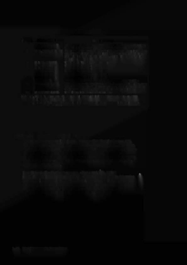
CPU LED Indicator Codes Table
Bllnkel
CPU Problem
Explanation
FI.eh ••
1 U25 RAM FAILURE U25 RAM could not be used properly (NO olher tests are performed;
Ihe game Is locked here, until the game Is turned off).
2
MEM. PROT. FAILURE This message means thst (A) the Coin Door may be shut ; (8) the Mem-
ory Protect Switch may be stuck In the ON position; (C) the memory
protect logic Is protecting the memory; or (D) a U25 RAM failure Is
occurring . (See Note 1)
3 U51 PIA FAILURE
U51 has a malfunction. (See Note 2)
4
U38 PIA FAILURE
U38 has a malfunction. (See Note 2)
5
U41 PIA FAILURE
U41 has a malfunction. (See Note 2)
8
U42 PIA FAILURE
U42 has a malfunction. (S.e Note 2)
7
U54 PIA FAILURE
U54 has a malfunction. (see Note 2)
8
U10 PIA FAILURE
U10 has a malfunction. (See Note 2)
9
IRQ FAILURE
IRQ has a malfunction. It may be missing or too fast or too slow.
10
U27 ROM FAILURE U27's Internal checksums do nOI match. It may be a ROM failure, or Its
associated connections and connectlngdevlces are causing It to ap-
pear
10
have a problem. (The following U26 lest Is skipped.)
1 1
U26 ROM FAILURS U26's Internal checksums do not match.
Not •• : 1, This tast assumes that the Coin Door Is OPEN; It
1&
Initiated ONLY by pressing the CPU
Diagnostic Switch (SW2).
2. Alternatively, Its associated connections or connecting devices are causing the IC to ap-
pear to have problems.
SYSTEM-ll B MEMORY CHIP TEST
A new feature Is now Included In the Memory Chip Test for System lIB,
During power-up, the CPU performs a self-testing routine. When all tests
are satisfactory, the game proceeds to the Attract Mode, allowing players to
use the game. Whenever a portion of the testing does not produce
satisfactory results, the game displays a message, before proceeding to the
next portion of the testing. ONLYafter all tests are satisfactory does the
game allow play to begin.
In addition to the displayed message, when a test fails, LED 2
('DIAGNOSTIC')mounted on the CPU Board can be observed to determine
the probable cause of the problem. This LED blinks, or flashes, a certain
number of times to identify the probable cause, as described in the CPU
LED Indicator Codes Table. The operator can also reset the program
by pressing the CPU Switch (SW2) on the edge of the CPU Board.
1-42 Test/Diagnostic Procedures