Basic HTML Version


lAMP MATRIX
Yellow (8+)
_@_
Red
I~
1
2
3
4
5
6
7
8
Yellow-
Yellow-
Yellow-
Yellow-
Yellow-
Yellow-
Yellow-
Yellow-
Brown
Red
Orange
Black
Green
Blue
Violet
Gray
J121-1
J121·2
J121·3
J121-4
J121·5
J121-6
J121-7
J121·9
w
096
0100
095
099
094
098
093
097
1
Red-
MONSTER.
RIGHT
OUARTER
LEFT
GUITAR CREATURE LEFT FRANK
MUCK
Brown
MOSHPIT
RAMP
MOOM
RETURN
ARM
J125-1 0104
ARROW
(2)
11
21
31
41
51
61
71
81
2
Red-
HALF
ROCK
LEFT BLUE
LEFT
DRUMS
BRIDE
LEFT FRANK SEAWEED
Black
MOON
C.D.
TARGET
OUTLANE
LEG
J125·20108
(2)
12
22
'32
42
52
62
72
82
3
Red-
FRANK
RIGHT
TOMB
THREE·
BASS
FRANKEN·
FRANK
ALGAE
Orange
ARROW RETURN TREASURE OUARTERS
GUITAR
STEIN
TORSO
J125-40103
MOON (2)
13
23
33
43
53
63
73
83
4
Red-
DRAC-
FULL MOON DRACULA RIGHT BLUE KEYBOARD
MUMMY
FRANK
POND SCUM
Yellow
ATTTACK
FEVER
STANDUP
TARGET
HEAD
J125-5 0107
(2)
TOP
14
24
34
44
54
64
74
84
5
Red-
EXTRA
RIGHT
RIGHT TOP LEFT RAMP MICRO·
WOLFMAN
RIGHT
CENTER
Green
BALL
GARGLE
LANE
ARROW PHONE
FRANK LOOP ARROW
J125-60102
LEG
2
15
25
35
45
55
65
75
85
6
Red-
MONSTERS
RIGHT
CENTER LEFTPRIMP SAXOPHONE DRACULA
RIGHT
CENTER
Blue
OF
WARMUP
TOP LANE
FRANK LOOP ARROW
J125-7 0106
ROCK
ARM
1
16
26
36
46
56
66
76
86
7
Red-
MONSTER
RIGHT
LEFT TOP LEFT WARM CENTER
RIGHT
LEFT LOOP
LAUNCH
Violet
BASH
PRIMP
LANE
UP
LOOP
OUTLANE
ARROW BUTTON
J125-80101
ARROW 3
17
27
37
47
57
67
77
87
8
Red-
MUMMY RIGHT LOOP DRACULA
LEFT
CENTER SHOOT AGAIN
NOT
START
Gray
MAYHEM ARROW STANDUP GARGOYLE
BLUE
USED
BUTTON
J125-9 0105
BOTTOM
TARGET
18
28
38
48
58
68
78
88
J1XX = Power Dnver Board
LAMP MATRIX CIRCUIT
:--------------c~I;~-~-(;~~-~;i;)-------:
;:1av -------------------:
-'C""O::.,:L::,::U""M:;.,;N""""'A-+:='B-+-::c=-
I
I
H L OF'F'
:
LS240
LS374
:
L H ON
I
I
:
J1XX
I
:
I
I
I
I
I
:
J1XX
I
I
I
I
I
I
I
I
,
I
I
I
I
I
:
I
IL.
.J
PLAYF'IELD
Red-X XX
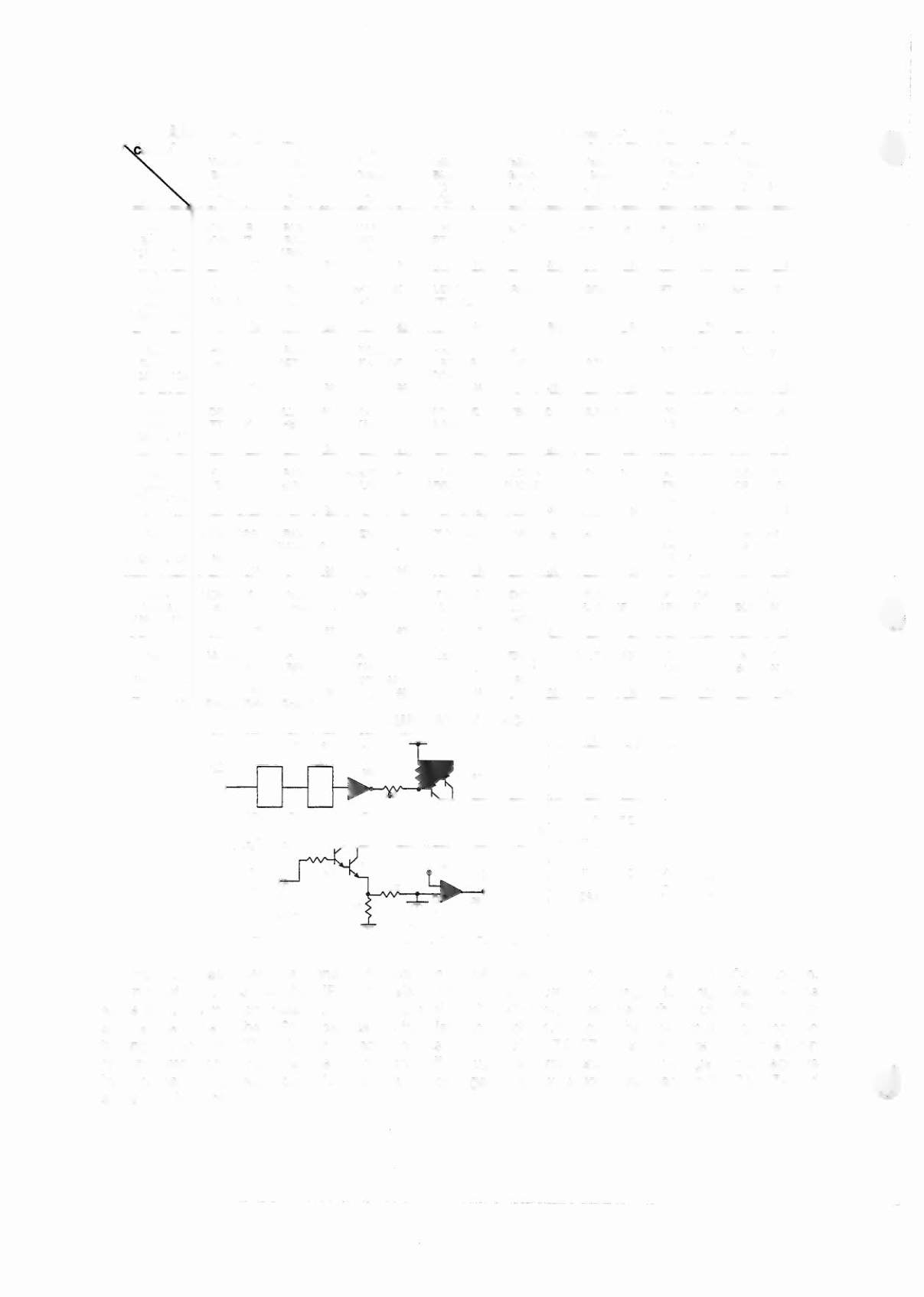
The microprocessor sends a signal to the column circuit causing the output of the UNL-2803 to toggle.
When point "A" drops low, the TIP107 transistor conducts and point "8" changes to a high state. At the
same time, the microprocessor drives the input of the 74LS74 low, causing a high at output
"P.
A high
state at the base of the TIP102 causes the transistor to conducts, bringing the row circuit to ground and
turning the lamp on. The microprocessor changes the input of the 74LS74 to a high state to turn the lamp
off. In overcurrent conditions, the lamp is shut off through the comparator.
If the voltage at the negative
input of the LM339 rises above 1.4V, the output changes to a low, which is fed back to the 74LS74 and
shuts the circuit off.
3-4