Basic HTML Version


DEDICATED SWITCHES
r-------,
:CPU :
:BOARD:
I
I
I
J205
I
I
I
r--
: Orange-Brown (U17-5)
D1
,--
,--
I
1
14
4
I
I
I
I
Orange-Red (U17-5)
02
I
,"u-
2
13
5
I
I
I
Oranqe-Black (U17-5)
03
I
"-0-
3
12
6
I
I
I
Orange-Yellow (U17-5)
04
I
4
17
I
I
Oranqe-Green (U17-5)
05
11
o
"u-
6
7
I
(U17-5)
06
I
,"u-
I
Orange-Blue
I
10
8
7
I
:
I
Orange-Violet
(U17-5)
07
~~
8
I
I
8
9
I
Orange-Gray (U17-5)
08
I
"-0-
9
I
I
9
11
I~
I
Black
I
15
3
I
:-
'----
I
I
I
I
I
r-------------------,
:
COIN DOOR :
I
INTERFACE
:
J1
BOARD
3 :
J
I
I
I
I
I
I
L
..J
I
I
L
..J
Coin Acceptor Switches
01 - Left Coin Chute
02 - Center Coin Chute
03 - Right Coin Chute
04 - Fourth Coin Chute
Control Switches
05 - Normal Function, Service Credits; Test Function, Escape
D6 - Normal Function, Volume Down; Test Function, Down
D7 - Normal Function, Volume Up; Test Function, Up
D8 - Normal Function, Begin Test; Test Function, Enter
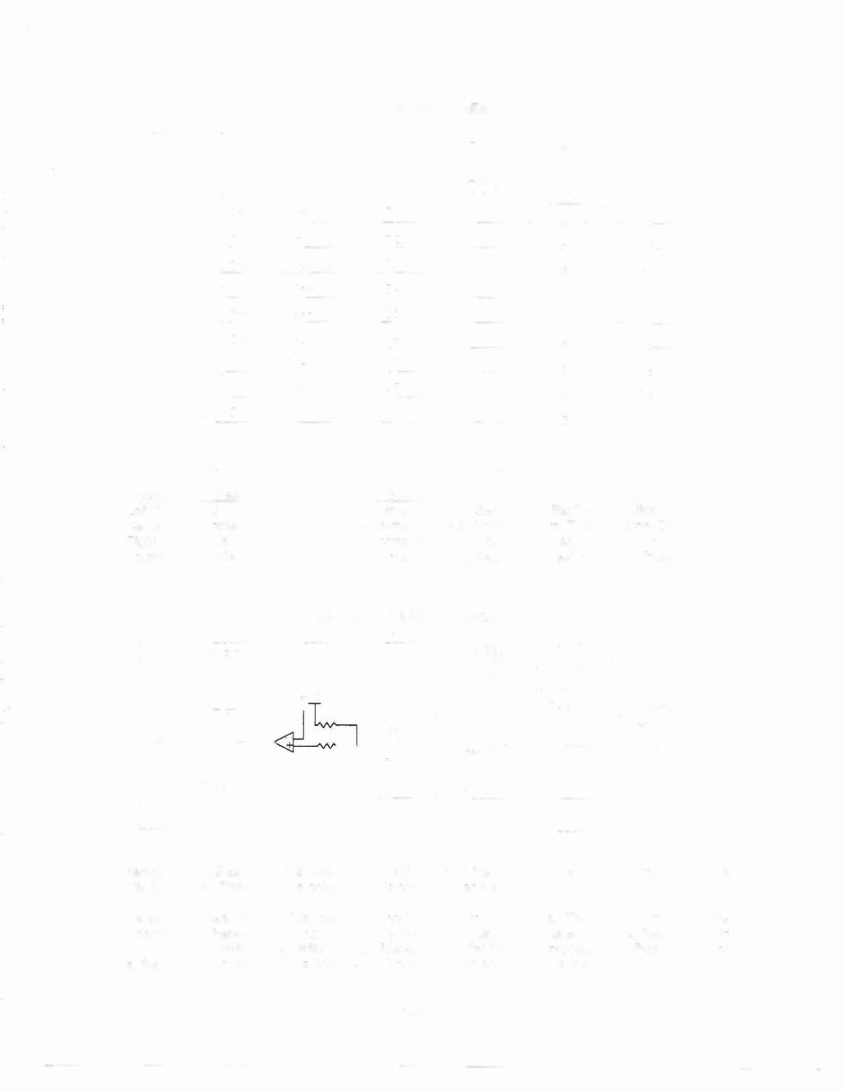
DEDICATED SWITCH CIRCUIT
CPU BOARD
SWITCH
+5V
LS374SC
Dedicated Input
The dedicated switches operate similar in the matrix, except that instead of a column circuit there is a
direct tie to ground. Therefore, the column side is constantly active (low).
When a switch closes, the row side (dedicated input) of the circuit activates. The "+" input to the LM339
drops below +5V, therefore the output is low. Since the row circuit (dedicated input) is tied directly to
ground through the switch, the switch is considered closed by the microprocessor.
When the switch
opens, the" +" input to the LM339 is above +5V, it output is high and the row is inactive.
3-3