Basic HTML Version


•
•
•
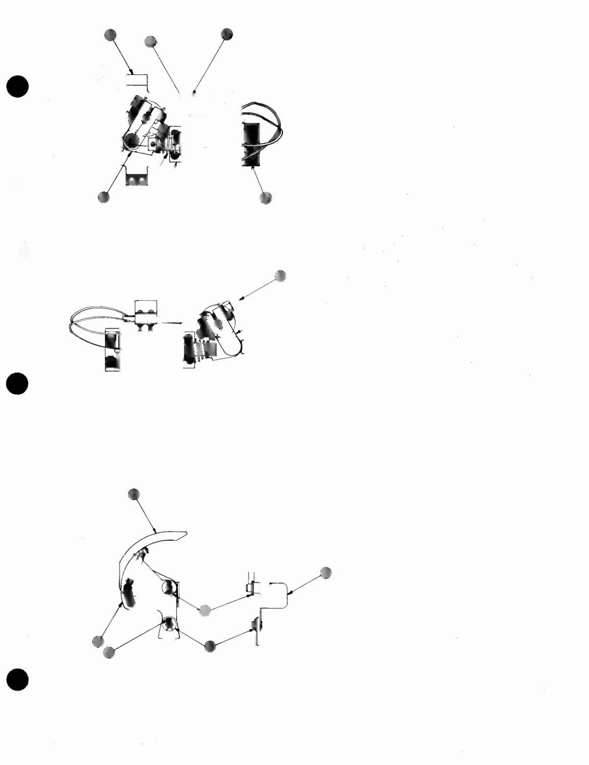
C-9952-R FLIPPER ASSEMBLIES
ITEM PART NO.
DESCRIPTION
1
B·10655·R
Crank Link Assembly
2
C·9954·R
Flipper Base/Lane Change Assembly
2a
03·7811
End of Stroke ~ Switch
2b
SW·1A·150
Lane Change
WI
ch
2c
03·7568
Flipper Bushing
2d
A·10280
Flipper Stock Bracket Assembly
3
01·7695
Solenoid Bracket
4
10·376
Coil Plunger Spring
5
FL 23/600·30/2600 Flipper Coil
6
23·6577
Bumper Plug
NOTES:
1 Each Flipper Assembly is mounted below Ihe playfield,
in con-
junction with the plastic flipper and shaft (20·9250) and flipper
rubber (23·6519) (on the upper side of Ihe playfield).
2 The tip of the EOS Switch must travel
.015 (~.010,
- .000 inch),
before the contacts fully open with the flipper in the actualed
position.
The EOS Switch contacts must have a gap of .062
(:!:
.015) inch. Any adjustment
of the EOS Switch must be made at
a minimum distance of .25 inch from the switch body
3 The Lane Change Switch musl have a gap of .046
(:!:
.015) inch,
when fully open
4 All moving elements of the assembly must operate freely without
any evidence of binding
5 Coil plunger spring must fit within the four lugs of the solenoid
bracket
6 For coil
replacement,
remove solenoid bracket. (item 3) to pre-
vent screw damage
Use Loclite when reassembling flipper stop bracket screws.
8 When using bumper plug on older flipper assemblies,
readjust
flipper position.
9 Solid color grey (or blue) wire connects to the banded end of the
diode, mounted on the connector end of flipper coil (item 5). Wire
with trace color connects to the unbanded end of the diode.
2
C-9953-L UNIQUE PARTS
ITEM PART NO.
DESCRIPTION
1
2
B·10655·L
C·9957-L
Crank Link Assembly, Left
Flipper Sub Base Assembly
3
2
B-9361-R-3 BALL EJECT
ASSEMBLY-RIGHT
ITEM PART NO.
DESCRIPTION
1
A·6949·R
Spring Plate
2
A·6950·R
Mounting Bracket Assembly
3
A-7471-R
Eject Cam Assembly
4
A·5103
Coil Plunger Assembly
5
10-362
Spring·Eject
6
12·6227
Hair Pin Clip
7
4700·00030·00 17/64 x 1/2 x 15G
8
4700·00103·00 17/64 x 1/2 x .015