Basic HTML Version


Game Control Locations
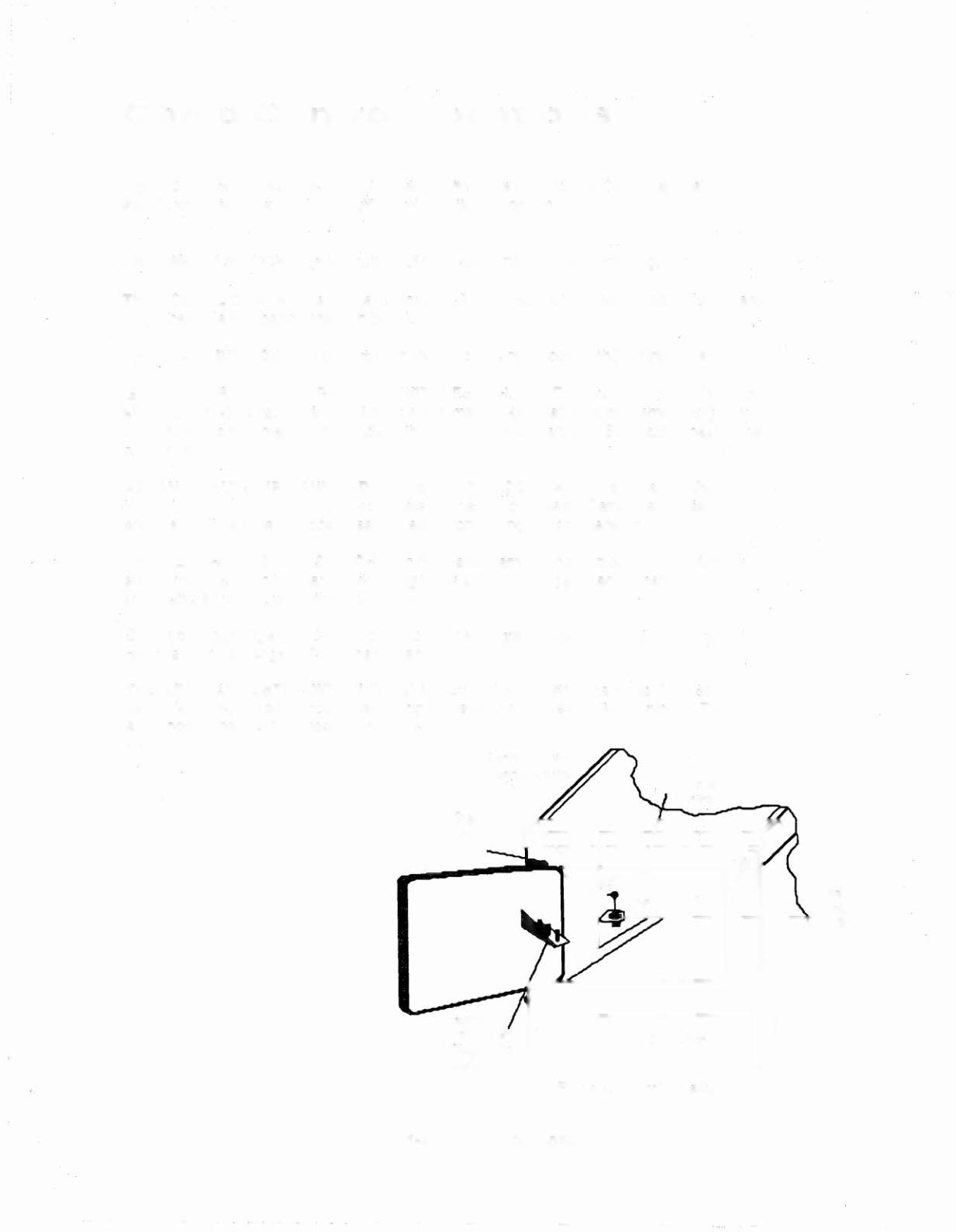
Figure 2 shows the locations of the following switches, except for the CPU Diagnostic
switch, which is shown in the Circuit Board Locations Diagram.
THE ON-OFF SWITCH is on the bottom of the cabinet near the right front leg.
THE VOLUME CONTROL is on the left inner wall of the cabinet on the tilt mechanism board.
It is accessible by opening the coin box door.
THE START BUTTON is a pushbutton to the left of the coin door on the cabinet exterior.
GAME ADJUSTMENT/DIAGNOSTIC SWITCHES.
DR. DUDE
allows the operator to control
all game adjustments, obtain bookkeeping information, and diagnose problems, using only
three switches mounted on the inside of the coin door, along with the Start button beside the
coin door.
ADVANCE, AUTO-UP/MANUAL-DOWN,
and HIGH-SCORE RESET are the switches
located on the inside of the coin door. Refer to the text discussing Game Status Displays
and the Test/Diagnostic Procedures for details conceming button operation.
THE MEMORY PROTECT SWITCH is on the inside frame of the coin door. This interlock
switch must be open to clear bookkeeping totals and to make game adjustments. It
automatically opens, when the coin door opens.
On the previous page, the Circuit Board Locations Diagram shows the locations of the CPU
Board switch (left edge of CPU Board, Backbox View).
THE CPU DIAGNOSTIC SWITCH (SW 2) is mounted on the left edge of the CPU Board
near a large, socketed microprocessor Chip. This switch initiates the Memory Chip Test
explained in the Test/Diagnostic Procedures.
Start
,,
On-Off Switch
Figure 2. Control Locations
1-4 Control Locations
' - -- - -- - - - - --