Basic HTML Version


G10 Error
The security chip is incorrect or faulty. If this occurs, replace the security chip.
G11 Checksum Error.
The game ROM checksum is invalid. If this occurs replace the game ROM.
Time and Date Not Set.
The real time clock is not set. Go to U.4 of the Utilities Menu and set the time and date.
Factory Settings Restored.
This message indicates that the CMOS RAM (U8) no longer retains any custom Pricing or Game
Adjustment settings and has reverted to factory default settings. Generally, the following CPU checks
will isolate the cause of the CMOS RAM memory failure. The voltages at pin 28 and pin 26 of U8
should be +5V (game turned On) and at least +4V (game turned Off). When the voltage drops below
+4V, memory reset occurs. Check the batteries and battery holder. Be sure that the batteries are
good and that there is no contamination on the battery holder terminals. Turn the game OFF, and
use an ohmmeter to check diodes 01 and 02 on the CPU Board. 01 should read 0 ohms when
forward-biased and infinite ohms when reverse-biased. 02 should read 15 ohms when forward-
biased and infinite ohms when reverse-biased. {Readings taken with an analog meter.)This
message can also indicate that there is an open diode on a 50V coil circuit and noise is entering the
circuit.
CPU and Audio Visual Board Error Codes
The CPU has three LED's, 201, 202, and 203. At game turn-on, LED 201 and LED 202 are on, LED
203 is off. During normal operation LED 201 is off, LED 202 is on, and LED 203 is flashing. If the
system detects and error the following happens:
CPU BOARD
Center LED blinks once
LED ERROR CODES Center LED blinks twice
Center LED blinks three times
=
G11 ROM Failure
= U8 RAM Failure
=
G10 Security Chip Failure
Upon game turn-on you will hear one of the following.
AUDIO VISUAL BOARD 1 Beep = Audio Visual Board is OK
BEEP ERROR CODES 2 Beeps
=
S2 Failure
3 Beeps
=
S3 Failure
4 Beeps = S4 Failure
5 Beeps
=
S5 Failure
6 Beeps
=
S6 Failure
7 Beeps
=
S7 Failure
10 Beeps
=
Audio Static RAM Failure
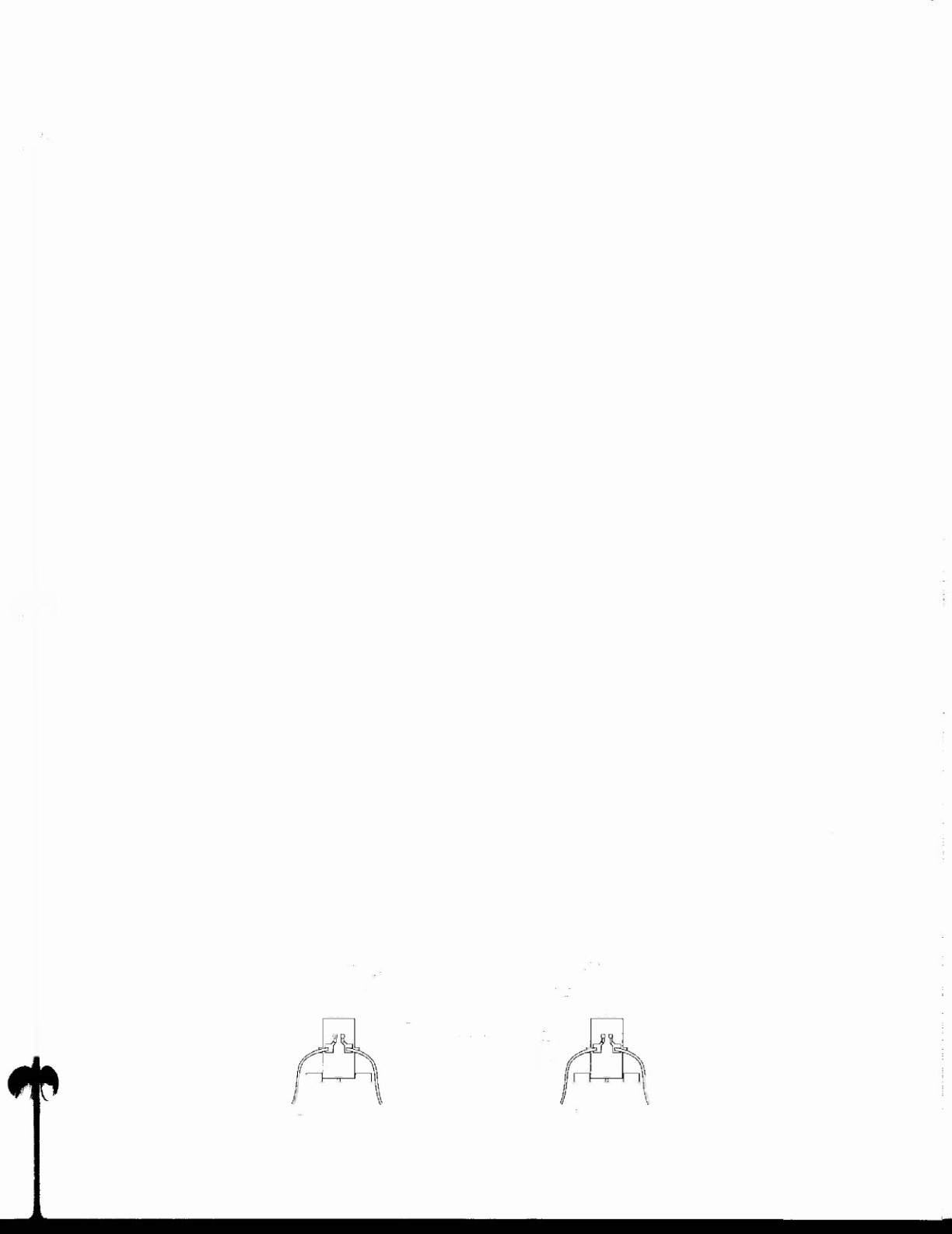
Opto Theory
The opto receiver (Photo Transistor) should be approximately 0.1 - 0.7 volts when the opto beam is
unblocked and approximately 11 - 13 volts when the opto beam is blocked. The opto transmitter
(LED) should always be approximately 1.4 volts.
Note:
The transmitter (LED) is larger than the
receiver (Photo Transistor); it protrudes further from its case.
I FD Board
Photo 1ronsis.or Bocre
T'ansr~:Lr.r
Receiver
I.H 1
VOlts
O.I-O.7V Unbloc,ed
I'
IJV moc\e<J
1-41