Basic HTML Version


Service Set-Up Procedure
NOTE: All monitors are equipped with automatic degaus-
sing coils which effectively demagnetize the picture tube
each time the monitor is turned on. Thedegaussing coils will
operate any time the set is turned on after having been off for
at least five minutes.
The degaussing effect is confined to the picture tube since
the coils are mounted on the ferrous tube shield. Should any
part of the chassis or cabinet become magnetized. it will be
necessary to degauss the affected area by means of a manual
degaussing coil. Move the coil slowly around the CRT face
area, then slowly withdraw for a distance of six feet before
disconnecting the coil from the AC power supply.
Normally little, if any adjustment should be necessary.
However, when a picture tube, yoke or similar component is
reptaced. preliminary static convergence should be done
before attempting purity adjustment, and so on.
Set up should be done in a north/south direction. Horizontal
and vertical centering taps should be set to the centre
position if a major component has been changed.
1.0 Purity
1.1 Loosen yoke retaining clamp (figure 2), remove
adhesive material fixing wedges to CRT. Remove
wedges completely and clean off dried adhesive from
picture tube and wedges.
1.2 A small quantity of "nail polish" has been used to lock
the purity convergence rings in place. This seal must
be broken with a sharp tipped instrument before any
adjustments are attempted. Some models also use a
locking ring at either end of the purity and
convergence rings. This must be loosened before
adjustments are made. It goes without saying that
upon completion of all adjustments, the lock must be
reset and/or a dab of paint or nail polish must be re-
applied to edge of rings to prevent movement.
1.3
Connect an appropriate signal source, eg: Electro-
home RGB generator producting a white field plus
individual red, green and blue fields.
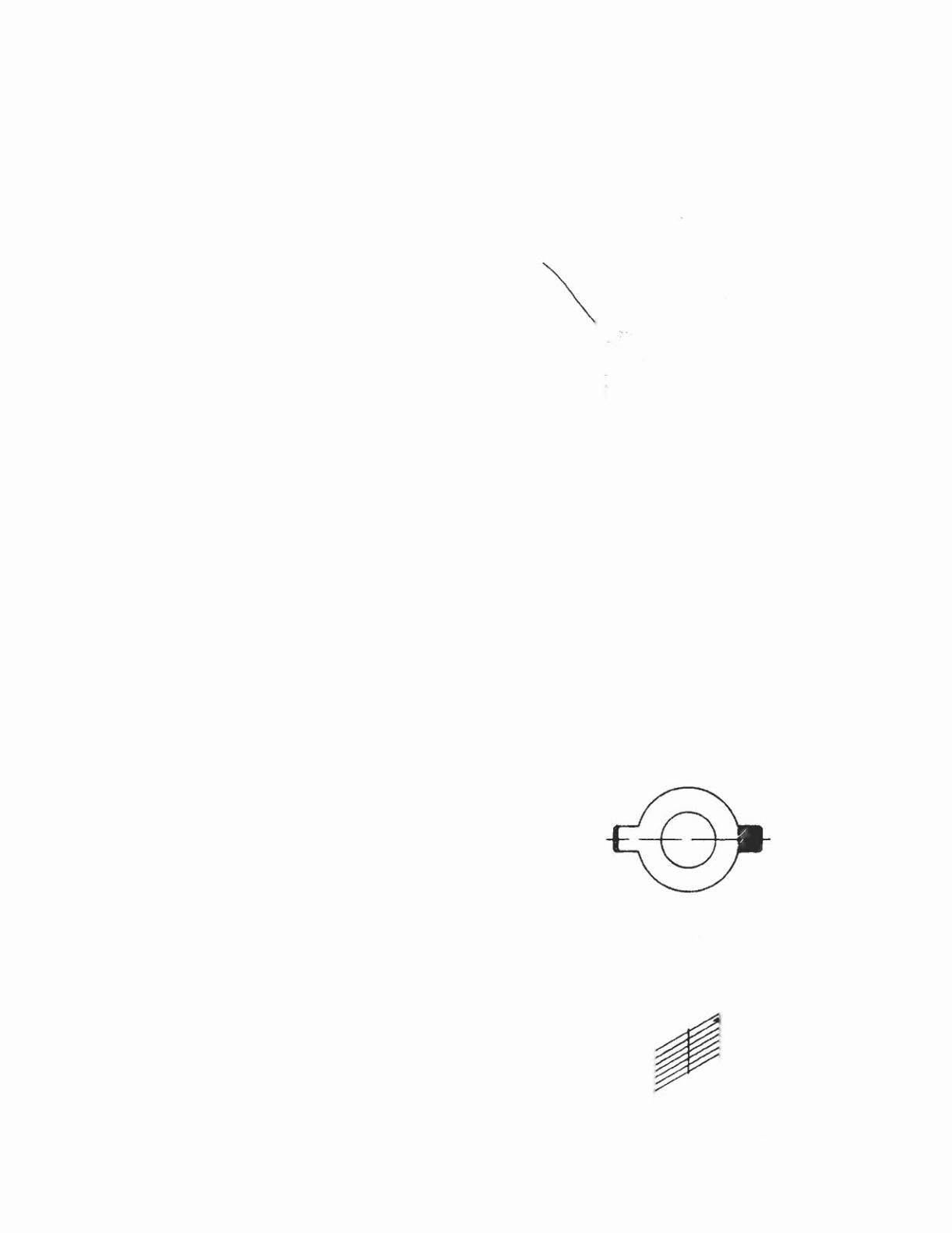
1.4 Bring the long and short purity tab protrusions in line
with each other to obtain near-zero magnetic field
(figure 4) (In some cases bring the flat and indented
tabs together to obtain zero field). Protrusions can
then be vertical, horizontal or at any convenient angle
to start.
1.5 Turn off the green and blue fields and adjust setup
controls to produce a red field. (See fig. 3)
1.6 Pull the deflection yoke back so that a red band
appears in the centre of the screen.
1.7 Spread the tabs apart as little as necessary and rotate
both rings together to center the red band horizontally
on the face of the CRT (approximate). (See Fig. 5)
1.8 Slide the yoke towards the bell of the picture tube
slowly to obtain a uniform red field (pure in color)
across the entire tube face. Juggle back and forth
slightly as necessary. Lightly tighten yoke retaining
clamp.
1.9 Momentarily switch on a cross-hatch signal and rotate
yoke to level the pattern on the face of CRT.
1.10 Return generator to regain red raster.
1.11 Turn off red field and check for pure field for each of
the green and blue fields. Reposition yoke if necessary
to obtain optimum purity on all fields.
1.12 Tighten yoke retaining clamp to prevent yoke shift or
rotation. (Do not install wedges at this time.)
31
'l'OKE ClAI.A~ 3CAEW
!
HIONT PUPil'!
••.•..•.GNfTS
"·POLE CON\I£AGfI'4Cf I.oIAGNETS
{
REAA6 PQ(fi.ONVfAG(NCE
"'.GNfTS
/
lOCKJ"IG RING ON ~ INCH 'M)~ElS
CRT SOCKET P.C.B.
o
III
SLUE
curer
F VR
ORE EN DR lYE
(1J
d
GREEN C'-'TOrF'
VR
REO DRIVE
III
III
RED CIJTOF'F'
vR
'-
--J
Bt:
C .•••R[FUL Or '8'
ANO '8' BOOST VOLTAGES PRE;[NT ON p.e.e.
(REAR VIEW)
Lit the
pl'OtrUliofI'
co",.
in Ii •••.
Con".
Br.1'1Q
rh, V'M"
bind 10 thl
Cet'ltrl
Figure
2
Figure3
Figure 4
Figure 5